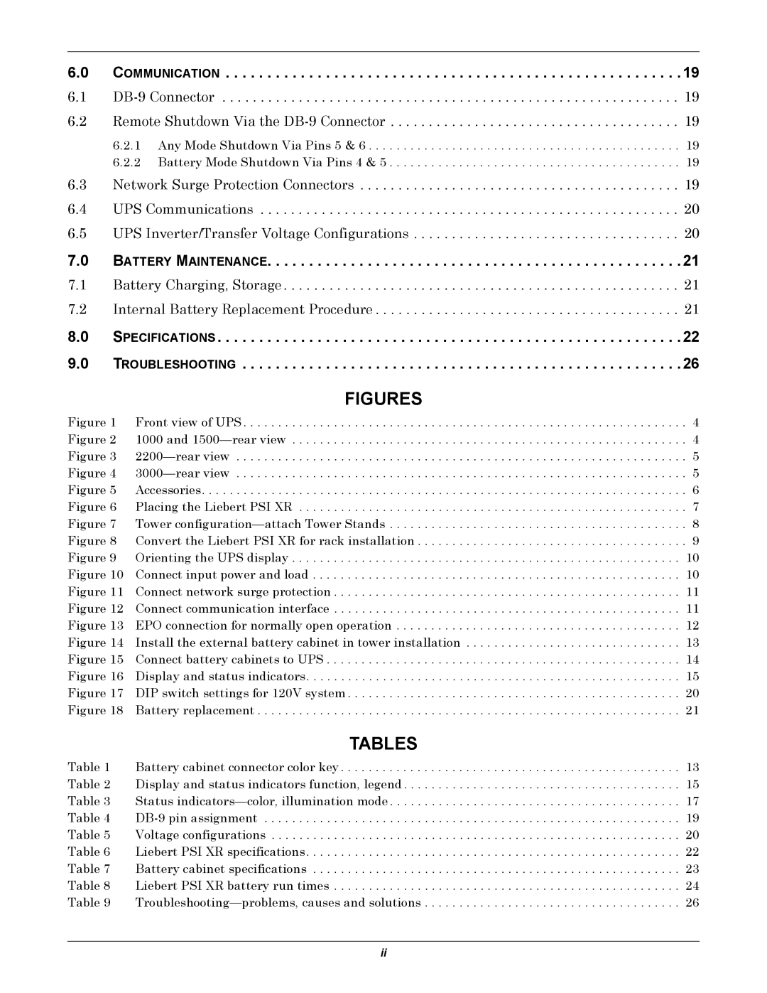
6.0 COMMUNICATION . . . . . . . . . . . . . . . . . . . . . . . . . . . . . . . . . . . . . . . . . . . . . . . . . . . . . . .19

6.1 DB-9 Connector . . . . . . . . . . . . . . . . . . . . . . . . . . . . . . . . . . . . . . . . . . . . . . . . . . . . . . . . . . . . 19 6.2 Remote Shutdown Via the DB-9 Connector . . . . . . . . . . . . . . . . . . . . . . . . . . . . . . . . . . . . . . 19

6.2.1 Any Mode Shutdown Via Pins 5 & 6 . . . . . . . . . . . . . . . . . . . . . . . . . . . . . . . . . . . . . . . . . . . . . 19 6.2.2 Battery Mode Shutdown Via Pins 4 & 5 . . . . . . . . . . . . . . . . . . . . . . . . . . . . . . . . . . . . . . . . . . 19

6.3 Network Surge Protection Connectors . . . . . . . . . . . . . . . . . . . . . . . . . . . . . . . . . . . . . . . . . . 19

6.4 UPS Communications . . . . . . . . . . . . . . . . . . . . . . . . . . . . . . . . . . . . . . . . . . . . . . . . . . . . . . . 20

6.5 UPS Inverter/Transfer Voltage Configurations . . . . . . . . . . . . . . . . . . . . . . . . . . . . . . . . . . . 20

7.0 BATTERY MAINTENANCE. . . . . . . . . . . . . . . . . . . . . . . . . . . . . . . . . . . . . . . . . . . . . . . . . .21

7.1 Battery Charging, Storage . . . . . . . . . . . . . . . . . . . . . . . . . . . . . . . . . . . . . . . . . . . . . . . . . . . . 21 7.2 Internal Battery Replacement Procedure . . . . . . . . . . . . . . . . . . . . . . . . . . . . . . . . . . . . . . . . 21

8.0 SPECIFICATIONS . . . . . . . . . . . . . . . . . . . . . . . . . . . . . . . . . . . . . . . . . . . . . . . . . . . . . . . .22 9.0 TROUBLESHOOTING . . . . . . . . . . . . . . . . . . . . . . . . . . . . . . . . . . . . . . . . . . . . . . . . . . . . .26

FIGURES

Figure 1 Front view of UPS . . . . . . . . . . . . . . . . . . . . . . . . . . . . . . . . . . . . . . . . . . . . . . . . . . . . . . . . . . . . . . . . 4 Figure 2 1000 and 1500—rear view . . . . . . . . . . . . . . . . . . . . . . . . . . . . . . . . . . . . . . . . . . . . . . . . . . . . . . . . . 4 Figure 3 2200—rear view . . . . . . . . . . . . . . . . . . . . . . . . . . . . . . . . . . . . . . . . . . . . . . . . . . . . . . . . . . . . . . . . . 5 Figure 4 3000—rear view . . . . . . . . . . . . . . . . . . . . . . . . . . . . . . . . . . . . . . . . . . . . . . . . . . . . . . . . . . . . . . . . . 5 Figure 5 Accessories. . . . . . . . . . . . . . . . . . . . . . . . . . . . . . . . . . . . . . . . . . . . . . . . . . . . . . . . . . . . . . . . . . . . . . 6 Figure 6 Placing the Liebert PSI XR . . . . . . . . . . . . . . . . . . . . . . . . . . . . . . . . . . . . . . . . . . . . . . . . . . . . . . . . 7 Figure 7 Tower configuration—attach Tower Stands . . . . . . . . . . . . . . . . . . . . . . . . . . . . . . . . . . . . . . . . . . . 8 Figure 8 Convert the Liebert PSI XR for rack installation . . . . . . . . . . . . . . . . . . . . . . . . . . . . . . . . . . . . . . . 9 Figure 9 Orienting the UPS display . . . . . . . . . . . . . . . . . . . . . . . . . . . . . . . . . . . . . . . . . . . . . . . . . . . . . . . . 10 Figure 10 Connect input power and load . . . . . . . . . . . . . . . . . . . . . . . . . . . . . . . . . . . . . . . . . . . . . . . . . . . . . 10 Figure 11 Connect network surge protection . . . . . . . . . . . . . . . . . . . . . . . . . . . . . . . . . . . . . . . . . . . . . . . . . . 11 Figure 12 Connect communication interface . . . . . . . . . . . . . . . . . . . . . . . . . . . . . . . . . . . . . . . . . . . . . . . . . . 11 Figure 13 EPO connection for normally open operation . . . . . . . . . . . . . . . . . . . . . . . . . . . . . . . . . . . . . . . . . 12 Figure 14 Install the external battery cabinet in tower installation . . . . . . . . . . . . . . . . . . . . . . . . . . . . . . . 13 Figure 15 Connect battery cabinets to UPS . . . . . . . . . . . . . . . . . . . . . . . . . . . . . . . . . . . . . . . . . . . . . . . . . . . 14 Figure 16 Display and status indicators. . . . . . . . . . . . . . . . . . . . . . . . . . . . . . . . . . . . . . . . . . . . . . . . . . . . . . 15 Figure 17 DIP switch settings for 120V system . . . . . . . . . . . . . . . . . . . . . . . . . . . . . . . . . . . . . . . . . . . . . . . . 20 Figure 18 Battery replacement . . . . . . . . . . . . . . . . . . . . . . . . . . . . . . . . . . . . . . . . . . . . . . . . . . . . . . . . . . . . . 21

TABLES

Table 1 Battery cabinet connector color key . . . . . . . . . . . . . . . . . . . . . . . . . . . . . . . . . . . . . . . . . . . . . . . . . 13 Table 2 Display and status indicators function, legend . . . . . . . . . . . . . . . . . . . . . . . . . . . . . . . . . . . . . . . . 15 Table 3 Status indicators—color, illumination mode . . . . . . . . . . . . . . . . . . . . . . . . . . . . . . . . . . . . . . . . . . 17 Table 4 DB-9 pin assignment . . . . . . . . . . . . . . . . . . . . . . . . . . . . . . . . . . . . . . . . . . . . . . . . . . . . . . . . . . . . 19 Table 5 Voltage configurations . . . . . . . . . . . . . . . . . . . . . . . . . . . . . . . . . . . . . . . . . . . . . . . . . . . . . . . . . . . 20 Table 6 Liebert PSI XR specifications. . . . . . . . . . . . . . . . . . . . . . . . . . . . . . . . . . . . . . . . . . . . . . . . . . . . . . 22 Table 7 Battery cabinet specifications . . . . . . . . . . . . . . . . . . . . . . . . . . . . . . . . . . . . . . . . . . . . . . . . . . . . . 23 Table 8 Liebert PSI XR battery run times . . . . . . . . . . . . . . . . . . . . . . . . . . . . . . . . . . . . . . . . . . . . . . . . . . 24 Table 9 Troubleshooting—problems, causes and solutions . . . . . . . . . . . . . . . . . . . . . . . . . . . . . . . . . . . . . 26

ii

Page 4
Image 4
Emerson 3000, 1500, 1000, 2200 user manual Communication, Battery Maintenance

1000, 1500, 2200, 3000 specifications

The Emerson 3000 is a cutting-edge control system designed to enhance the efficiency, reliability, and precision of industrial operations. Employed across various sectors such as oil and gas, pharmaceutical, food and beverage, and power generation, the Emerson 3000 has gained recognition for its robustness and versatility.

One of the main features of the Emerson 3000 is its advanced process control capability. With integrated control algorithms, it can optimize complex processes in real-time, resulting in significant improvements in production rates and reduced operational costs. The system's predictive analytics capabilities enable operators to anticipate equipment failures and maintenance needs, allowing for proactive management and minimizing downtime.

The Emerson 3000 features a modular architecture, providing flexibility for scaling and customization. Operators can easily tailor the system to fit specific application needs, whether it requires additional control loops or integration with other systems. This adaptability is particularly beneficial for facilities planning for future expansions or modifications.

Another technology highlight of the Emerson 3000 is its seamless integration with the latest Internet of Things (IoT) advancements. The system is designed to communicate effectively with a variety of smart devices and sensors, harnessing data to create insightful analytics that drive operational excellence. This connectivity empowers businesses to leverage big data for improved decision-making and increased agility.

Additionally, the Emerson 3000 incorporates state-of-the-art cybersecurity measures to safeguard critical data and operations. With built-in security protocols and regular updates, the system protects against emerging cyber threats, ensuring the integrity of the control network.

User experience is also a focal point of the Emerson 3000. The intuitive graphical user interface presents complex data in a user-friendly format, making it easier for operators to monitor system performance and respond to alerts quickly. This ease of use contributes to enhanced safety and operational efficiency.

In summary, the Emerson 3000 represents a fusion of advanced process control, modular design, IoT connectivity, robust cybersecurity, and user-centric interface, making it an ideal choice for industries seeking to enhance their operational performance while adapting to ever-evolving technological landscapes.