Tank Gauging System
Installation Manual
Page
Installation manual
Rosemount Tank Radar AB
Contents
Field Communication Unit
Remote Display Unit RDU40
BUS Modems
Junction Boxes
Connection to Computer Networks
Mechanical Installation
List of Drawings
Sensor Installation
Technical Data
Recovery of Packing Material
Recovery of Products
TOC-8
Introduction
Installation
General configuration of a TankRadar REX sys- tem
Installation
Manual Overview
Intrinsic Safety
Safety
Explosion Proof
Special Conditions for Safe Use
European Atex Directive Information
Radar Unit
Radar Tank Gauge
Schedule of Limitations
Transmitter Interface Card TIC
Certification label for the Temperature Multiplexer Card TMC
Temperature Multiplexer Card TMC
Certification label for the FF Adaptor Card FFA
FF Adaptor Card FFA
Certification label Atex for the Data Acquisition Unit
Data Acquisition Unit DAU
Approval label for the Remote Display Unit RDU40
Remote Display Unit 40 RDU
Installation Manual
Transmitter Head RTG 3900 REX
Description of 3900 REX
RTG 3900 transmitter head electronics
Transmitter Head Electronics
Field Communication Card FCC
Analog Processing Card APC
Relay Output Card ROC
Metrological Seal
Internal switch
External switch
Parabolic Antenna Gauge, RTG
Antenna Types
Horn Antenna Gauge, RTG
RTG 3950 Still Pipe Gauge
LPG/LNG Gauge, RTG
Local Readout Display
Data Acquisition Unit
DAU
Write Enable/Inhibit Switch
Temperature Sensors
Connecting the Data Acquisition Unit, DAU
Power Supply
Temperature Range
Selecting the temperature range
RDU 40 connected to the REX gauge
Remote Display Unit RDU40
Installation of RDU 40 master and slave
Back of RDU40
Data items
Two RDU 40 connected to the same REX
FCU Enclosure
Field Communication Unit
1 RS232 communication
Communication Ports
2 RS 485 communication
Write Inhibit/Enable Switch
Connection to a PC
Connecting the Field Communication Unit, FCU
Redundancy
Redundant FCUs, FBMs and workstations
Field Bus Modem
Bus Modems
DIN Rail Mounting
Field Bus Modem
3 TRL/2 Bus
Cable dimension Maximum Length
USB Communication
4 RS 232 Communication
USB Driver Installation
WizardWindowsXP / WizardWindowsXPUSB
Communicating with TankMaster
Operation Front Panel
10 RS 232 Interface
USB Interface
Power supply for RS-232
Specifications Explosion protection
LED indicators
Cable to Host PC
Enraf Bus Modem, EBM
System Type Required Steps Optional Steps Described below
Connecting the Enraf Bus Modem
Configuration
Installation Manual
Explosion Approval
Junction Boxes
Integrated Junction Box, JBi
Cable Inlets RTG
Design
2 JB 140-11 for EEx e environments
1 JB 140-15 for EEx i environments
Conduit outlets
Junction Boxes with Conduit Outlets
Junction Box JBT
Connection of Temperature Sensors
Junction Box JB 36/42
Connection of temperature sensors to JB 36/42 via cable
Connect to TankMaster for Inventory Data
Connect to the FCU for Quick Updates
Connection to Computer Networks
Connection to Computer Networks May
Installation Requirements
Mechanical Installation
10-1
Mounting a Horn Antenna Gauge
Free Space Requirements
10-2
10-3
Dimensions
10-4
Installation on the tank
10-5
Mounting the Parabolic Antenna Gauge
10-6
Inclination
Inclination Flange Ball model T30
Maximum inclination of flange towards the tank center
10-7
Inclination Flange Ball model T38-W
10-8
Free space requirements
10-9
Socket Requirements
Recommended Installation
10-10
Mounting the Flange Ball model T30
10-11
Mounting the Flange Ball model T38-W
10-12
10-13
Mounting the Antenna
10-14
10-15
10-16
10-17
10-18
10-19
Introduction
10-20
Mounting a Still Pipe Gauge
Still Pipe Requirements
10-21
Antenna size mm Pipe
Flange Requirements
10-22
Pipe Dimension Inch Max Area
Free space requirements RTG 3950 Fixed Version
10-23
10-24
Installation of the 3950 Fixed Version on the tank
10-25
10-26
10-27
Free space requirements RTG 3950 Inclined Version
10-28
10-29
10-30
Installation of the RTG 3950 Inclined Version
Mount the antenna on the lid
10-31
10-32
10-33
10-34
Connection
10-35
Mount the Waveguide
10-36
10-37
10-38
Temperature and Pressure Measurement
Mounting a LPG/LNG Gauge
Still Pipe
14. Still Pipe requirements
10-39
Reference Pin and Reflector
10-40
16. Mounting of reflector on pipe 4 inch SCH
10-41
Extension Pipe for Minimum Distance
10-42
10-43
10-44
10-45
10-46
11-1
Electrical Installation of the REX Gauges
Cabling for Power Supply
60 VDC 24 VDC
11-2
115 VAC 60 VAC
Grounding
11-3
Cabling for TRL/2 Bus
11-4
Connecting the Radar Tank Gauge
Terminated
11-5
Cable Outputs
11-6
Option W12 connection
Integrated Junction Box
11-7
Wiring
Intrinsically safe side EEx
Connection Description
Non-Intrinsically safe side EEx e
11-8
Options
11-9
Analog output passive Connection Description
Analog output active Connection Description
11-10
11-11
Tiway Connection Description
11-12
Tiway bus +
Tiway bus
11-13
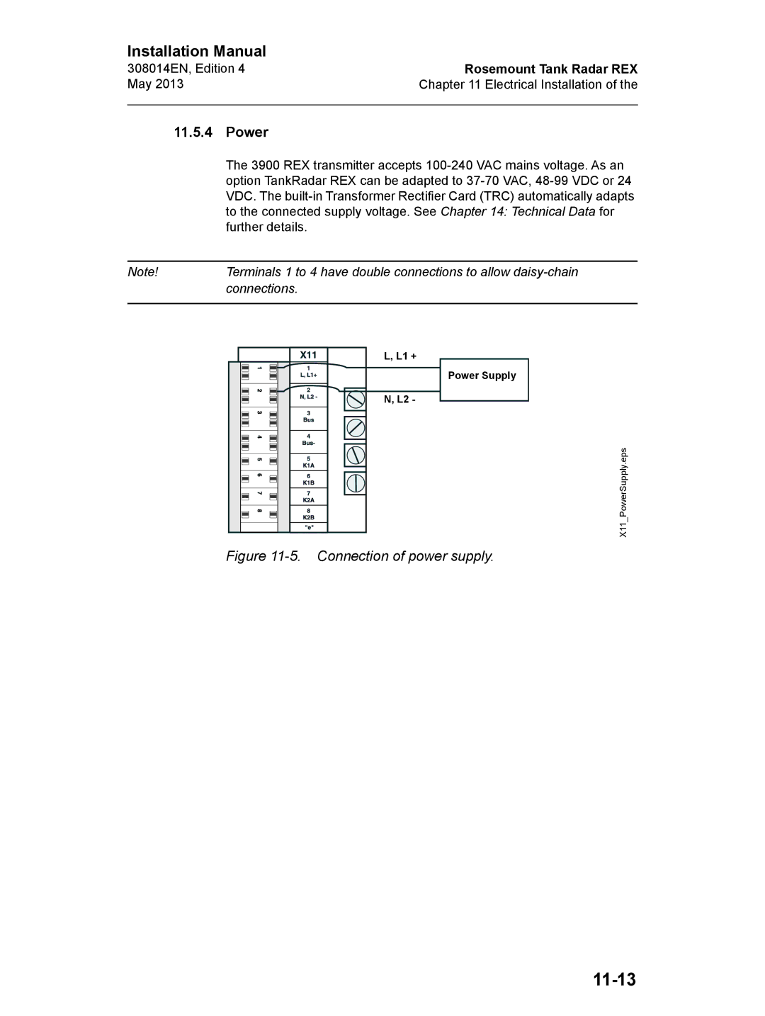
Power
11.5.5 TRL/2 Bus
11-14
Relays
11-15
Normally Closed Normally Open
11-16
Analog Output
11-17
11-18
Connecting the Temperature Sensors
Spot Elements
Sensor
Sensor Connection
11-19
Average/Multiple Spot elements
Analog Inputs
11-20
Hart Slaves
11-21
11.5.11 DAU/RDU
11-22
12-1
Sensor Installation
Temperature Sensors
12-2
Installation of Multiple Spot Temperature sensors
Example
12-3
12-4
Sensor Installation May 12-5
Water Level Sensor
Mechanical Installation
12-5
Tank geometry for the Water Level Sensor
12-6
Tank Zero Level
12-7
Upper Range Value 20 mA = LA + Lower Range Value 4 mA =
Water Zero Level is above the Tank Zero Level
12-8
13-1
Mechanical Installation Drawings TankRadar REX
List of Drawings
Field Bus Modem, FBM
Electrical installation
13-2
Field Communication Unit, FCU
13-3
Data Acquisition Unit, Sdau
Remote Display Unit, RDU
Junction Boxes JB
Temperature / WLS sensors
13-4
14.1 RTG
Technical Data
14-1
Analog Inputs
14-2
14.1.3 Analog Output
14-3
14.2 RTG
14-4
14.3 RTG
14-5
14.4 RTG
14-6
14.5 RTG
14-7
Data Acquisition Unit, DAU
14-8
View/Software
14-9
Electrical
Mechanical
TRL/2
14-10
Numerics
Index-1
Index May
Index-2
May Index Grounding Potential equalizing network Group Bus
Index-3
Index-4
Radar beam
Index-5
Index-6
Supply voltage switch Field Communication Unit
Index-7
Index-8
Page
Emerson Process Management
Rosemount Tank Gauging local representative

