Controls and Indicators
off power to the output sockets and connected loads. Perform all necessary shutdown procedures on connected loads before pressing this button twice.
7.3Load Level Indicators (4 Green, 1 Amber)
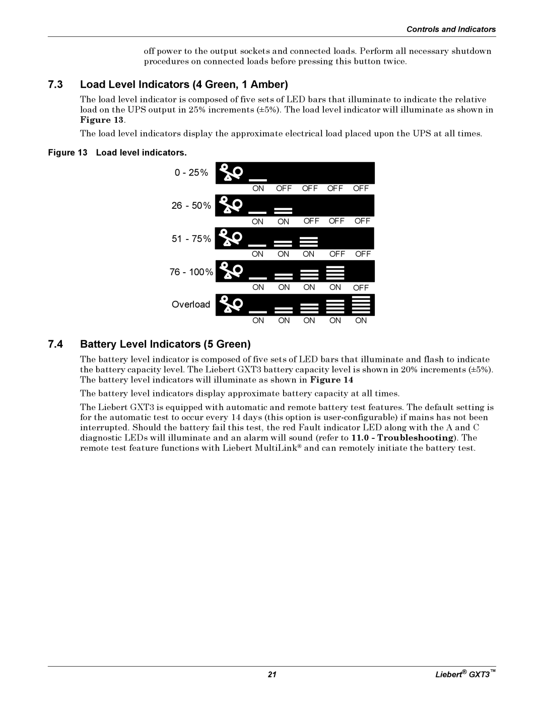
The load level indicator is composed of five sets of LED bars that illuminate to indicate the relative load on the UPS output in 25% increments (±5%). The load level indicator will illuminate as shown in Figure 13.
The load level indicators display the approximate electrical load placed upon the UPS at all times.
Figure 13 Load level indicators.
0 - 25%
26 - 50% ![]()
![]()
ON OFF OFF OFF OFF
ON ON OFF OFF OFF
51 - 75% ![]()
![]()
ON ON ON OFF OFF
76 - 100% ![]()
![]()
Overload ![]()
![]()
ON ON ON ON OFF
ON ON ON ON ON
7.4Battery Level Indicators (5 Green)
The battery level indicator is composed of five sets of LED bars that illuminate and flash to indicate the battery capacity level. The Liebert GXT3 battery capacity level is shown in 20% increments (±5%). The battery level indicators will illuminate as shown in Figure 14
The battery level indicators display approximate battery capacity at all times.
The Liebert GXT3 is equipped with automatic and remote battery test features. The default setting is for the automatic test to occur every 14 days (this option is
21 | Liebert® GXT3™ |