Controls and Indicators
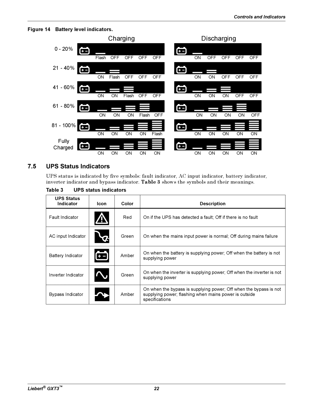
Figure 14 Battery level indicators.
|
| Charging |
|
| |
0 - 20% |
|
|
|
|
|
|
|
|
|
| |
|
|
|
|
|
|
| Flash | OFF | OFF | OFF | OFF |
21 - 40% |
|
|
|
|
|
|
|
|
|
| |
|
|
|
|
|
|
| ON | Flash | OFF | OFF | OFF |
41 - 60% |
|
|
|
|
|
|
|
|
|
| |
|
|
|
|
|
|
| ON | ON | Flash | OFF | OFF |
61 - 80% |
|
|
|
|
|
|
|
|
|
| |
|
|
|
|
|
|
| ON | ON | ON | Flash | OFF |
81 - 100% |
|
|
|
|
|
|
|
|
|
| |
|
|
|
|
|
|
| ON | ON | ON | ON | Flash |
Fully |
|
|
|
|
|
|
|
|
|
| |
Charged |
|
|
|
|
|
| ON | ON | ON | ON | ON |
Discharging
ON OFF OFF OFF OFF
ON ON OFF OFF OFF
ON ON ON OFF OFF
ON ON ON ON OFF
ON ON ON ON ON
ON ON ON ON ON
7.5UPS Status Indicators
UPS status is indicated by five symbols: fault indicator, AC input indicator, battery indicator, inverter indicator and bypass indicator. Table 3 shows the symbols and their meanings.
Table 3 UPS status indicators
UPS Status |
|
|
|
|
|
Indicator |
| Icon | Color | Description | |
|
|
|
|
|
|
Fault Indicator |
|
|
| Red | On if the UPS has detected a fault; Off if there is no fault |
|
|
| |||
|
|
|
|
|
|
|
|
|
|
|
|
AC input Indicator |
|
|
| Green | On when the mains input power is normal; Off during mains failure |
|
|
| |||
|
|
|
|
|
|
|
|
|
|
|
|
Battery Indicator |
|
|
| Amber | On when the battery is supplying power; Off when the battery is not |
|
|
| |||
|
|
| supplying power | ||
|
|
|
|
| |
|
|
|
|
|
|
Inverter Indicator |
|
|
| Green | On when the inverter is supplying power; Off when the inverter is not |
|
|
| |||
|
|
| supplying power | ||
|
|
|
|
| |
|
|
|
|
|
|
|
|
|
|
| On when the bypass is supplying power; Off when the bypass is not |
|
|
|
|
| |
Bypass Indicator |
|
|
| Amber | supplying power; flashing when mains power is outside |
|
|
|
|
| specifications |
|
|
|
|
|
|
Liebert® GXT3™ | 22 |
