MODEL
SENSOR WIRING AND SET-UP
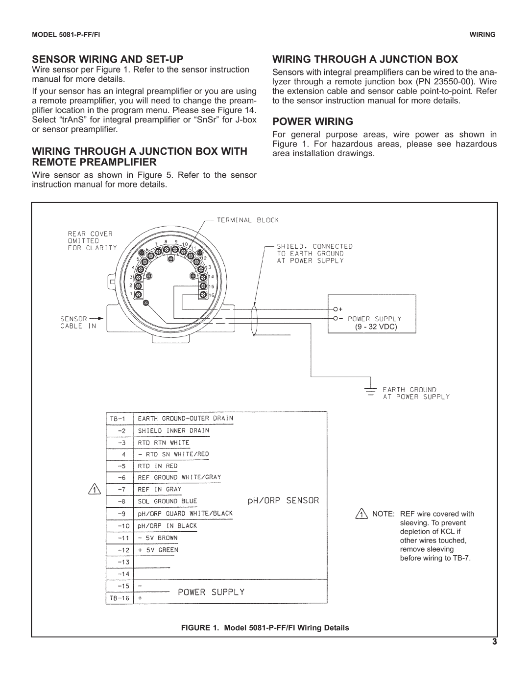
Wire sensor per Figure 1. Refer to the sensor instruction manual for more details.
If your sensor has an integral preamplifier or you are using a remote preamplifier, you will need to change the pream- plifier location in the program menu. Please see Figure 14. Select “trAnS” for integral preamplifier or “SnSr” for
WIRING THROUGH A JUNCTION BOX WITH REMOTE PREAMPLIFIER
Wire sensor as shown in Figure 5. Refer to the sensor instruction manual for more details.
WIRING
WIRING THROUGH A JUNCTION BOX
Sensors with integral preamplifiers can be wired to the ana- lyzer through a remote junction box (PN
POWER WIRING
For general purpose areas, wire power as shown in Figure 1. For hazardous areas, please see hazardous area installation drawings.
(9 - 32 VDC)
![]() NOTE: REF wire covered with sleeving. To prevent depletion of KCL if other wires touched, remove sleeving before wiring to
NOTE: REF wire covered with sleeving. To prevent depletion of KCL if other wires touched, remove sleeving before wiring to
FIGURE 1. Model 5081-P-FF/FI Wiring Details
3