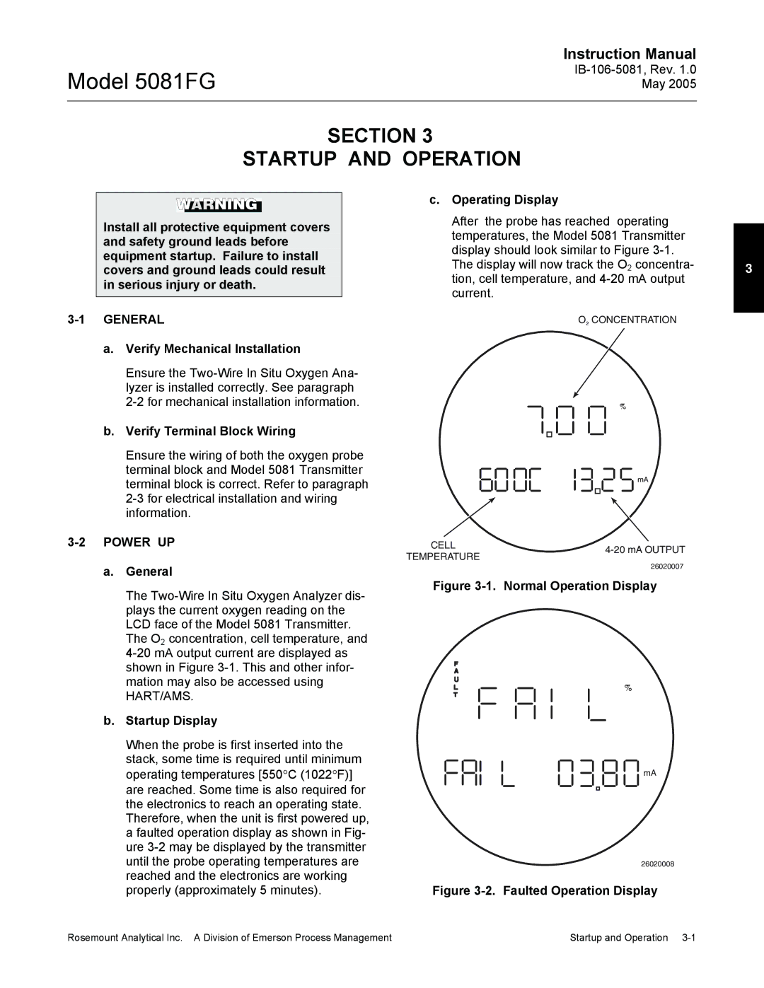
5081FG specifications
The Emerson 5081FG Series is a cutting-edge digital smart transmitter designed for various industrial applications, including oil and gas, chemical processing, and water treatment. Known for its accuracy and reliability, the Emerson 5081FG integrates an array of advanced technologies to enhance measurement capabilities and operational efficiency.One of the main features of the 5081FG is its multi-variable measurement, which allows for the integration of differential pressure, static pressure, and temperature readings into a single device. This capability significantly reduces the need for multiple instruments, leading to lower installation costs and improved data collection efficiency.
With Smart Wireless technology, the Emerson 5081FG offers robust wireless communication, making it ideal for remote or hard-to-reach locations. Its ability to transmit real-time data wirelessly enhances operational awareness and enables proactive maintenance decisions. The transmitter can easily connect to various process control systems for seamless integration and data sharing.
The 5081FG also incorporates Emerson's advanced diagnostics and predictive maintenance algorithms. These features continuously monitor the health of the transmitter and the processes it measures, alerting operators to potential issues before they escalate into serious problems. This proactive approach to maintenance not only improves safety but also minimizes downtime and maximizes productivity.
Another significant characteristic of the Emerson 5081FG is its rugged design, built to withstand harsh industrial environments. With an IP67 rating, it is resistant to dust and water ingress, ensuring reliable operation even in challenging conditions. The device is also designed to handle a wide range of temperatures and pressures, making it versatile for diverse applications.
User-friendly configuration and programming are facilitated by Emerson's intuitive software tools, which provide easy setup and calibration processes. This simplicity allows operators to optimize performance without needing extensive training or support.
In conclusion, the Emerson 5081FG is a powerful and reliable smart transmitter that addresses the needs of various industries. Its multi-variable measurement capability, wireless communication, advanced diagnostics, and rugged design make it an excellent choice for companies looking to enhance their operational efficiency and maintain high standards of safety and reliability. With the Emerson 5081FG, businesses can expect not only accurate measurements but also valuable insights that contribute to smarter decision-making.

