SECTION 1 INSTALLATION
ASCO 4000 Series Automatic
Remove the Shipping Skid
For large switches, open the front door and remove the four lag screws (2 in front, 2 in rear) securing enclosure to the wood skid.
Supporting Foundation
The supporting foundation for the enclosure must level and straight. Refer to the applicable enclosure outline drawing included with the 4ADTS for all mounting details including door opening space.
If bottom cable entry is used, the foundation must be prepared so that the conduit stubs are located correctly. Refer to the enclosure outline drawing for specified area and location. Provide cable bending space and clearance to live metal parts. When a concrete floor is poured, use interlocking conduit spacer caps or a wood or metal template to maintain proper conduit alignment.
Mounting
Refer to the outline and mounting diagram provided with the ATS; it shows all mounting details and instructions.
Protect the switch from construction grit and metal chips to prevent malfunction or shortened life of the automatic switch switch.
Mount the ATS vertically to a rigid supporting structure. Level all mounting points by using flat washers behind the holes to avoid distortion of the switch.
The controller is mounted on the cabinet door. An add- on DIN rail is provided for some optional accessories and is mounted below controller on the door.
should be tested to verify that they are not defective or have been damaged during installation.
Connecting Power Conductors
A Wiring Diagram is furnished with the ASCO 4000 Series 4ADTS (separate from this manual). Refer to this drawing. All wiring must be made in accordance with the National Electrical Code and local codes.
After the power cables have been tested, connect them to the appropriate terminal lugs on the transfer switch as shown on the wiring diagram provided with the switch. Make sure the lugs provided are suitable for use with the cables being installed. Standard terminal lugs are solder- less screw type and will accept the wire sizes listed on the drawings provided with the switch. Be careful when stripping insulation from the cables; avoid nicking or ringing the conductor. Remove surface oxides from cables by cleaning with a wire brush. When aluminum cable is used, apply joint compound to conductors. Tighten cable lugs to the torque specified on rating label.
Do not run cables in front of or behind the switch. Cables can be bundled on the right side of the switch. Maintain proper electrical clearance between the live metal parts and grounded metal: ½ inch minimum for
It is not necessary to remove the barriers from the transfer switches to install the cables. If you do remove them,however, be sure to reinstall the barriers carefully.
Bus Connections
For large switches use grade 5 hardware to connect bus to appropriate terminal plates. Wipe off the bus surfaces before they are joined. If the bus is very dirty, gently clean the surfaces with a
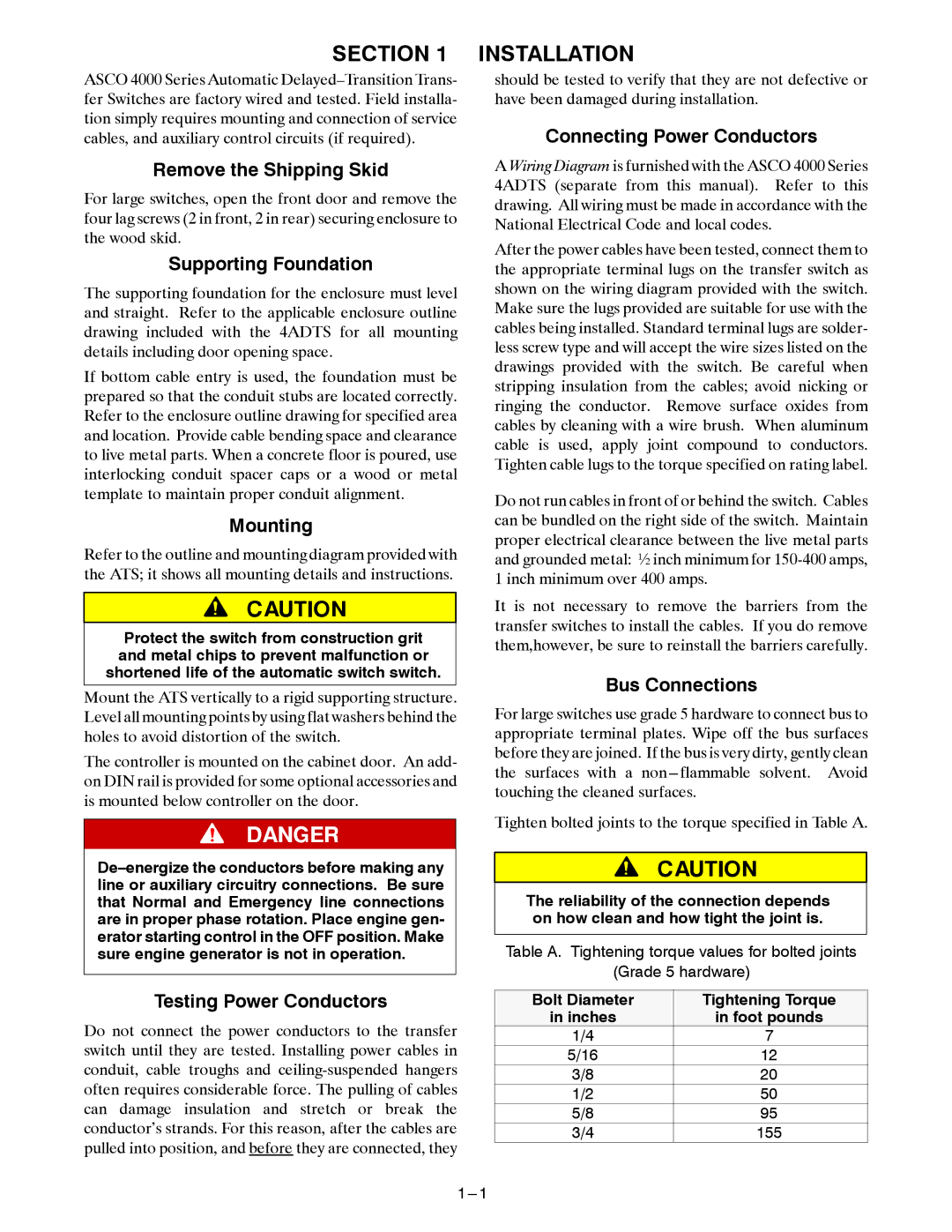
Tighten bolted joints to the torque specified in Table A.
The reliability of the connection depends on how clean and how tight the joint is.
Table A. Tightening torque values for bolted joints
(Grade 5 hardware)
Testing Power Conductors
Do not connect the power conductors to the transfer switch until they are tested. Installing power cables in conduit, cable troughs and
Bolt Diameter | Tightening Torque |
in inches | in foot pounds |
1/4 | 7 |
5/16 | 12 |
3/8 | 20 |
1/2 | 50 |
5/8 | 95 |
3/4 | 155 |