INSTALLATION (continued)
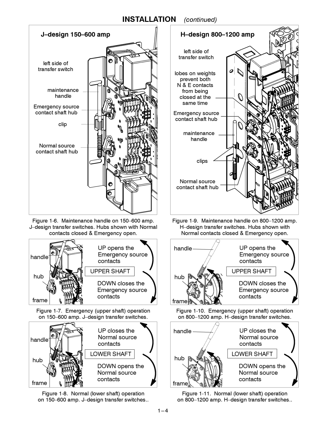
J–design 150–600 amp
left side of
transfer switch
maintenance
handle
Emergency source contact shaft hub
clip
Normal source
contact shaft hub
H–design 800–1200 amp
left side of
transfer switch
lobes on weights
prevent both
N & E contacts
from being
closed at the
same time
Emergency source contact shaft hub
maintenance
handle
clips
Normal source
contact shaft hub
Figure 1-6. Maintenance handle on 150–600 amp. J–design transfer switches. Hubs shown with Normal contacts closed & Emergency open.
Figure 1-9. Maintenance handle on 800–1200 amp.
H–design transfer switches. Hubs shown with Normal contacts closed & Emergency open.
| UP opens the | |
handle | Emergency source | |
contacts | ||
| ||
hub | UPPER SHAFT | |
DOWN closes the | ||
| ||
| Emergency source | |
frame | contacts | |
|
Figure 1-7. Emergency (upper shaft) operation on 150–600 amp. J–design transfer switches.
handle | UP opens the | |
| Emergency source | |
| contacts | |
hub | UPPER SHAFT | |
DOWN closes the | ||
| ||
| Emergency source | |
frame | contacts | |
|
Figure 1-10. Emergency (upper shaft) operation on 800–1200 amp. H–design transfer switches.
UP closes the
handleNormal source contacts
LOWER SHAFT
hub
DOWN opens the Normal source
frame ![]() contacts
contacts
Figure 1-8. Normal (lower shaft) operation on 150–600 amp. J–design transfer switches..
handle | UP closes the |
| Normal source |
| contacts |
hub | LOWER SHAFT |
| |
| DOWN opens the |
| Normal source |
frame | contacts |
|