TESTING & SERVICE (continued)
MANUAL LOAD TRANSFER
This procedure will manually transfer the load if the controller is disconnected.
Do not manually operate the transfer switch until both power sources are disconnected (all conductors deenergized).
1.Deenergize both the normal and emergency source conductors (remove fuses or open circuit breakers).
2.Use the maintenance handle to manually operate the transfer switch to the opposite source. First open the closed contacts, then close the other contacts. Do not try to close both Normal and Emergency contact. See Manual Operation on page
3.Then remove the maintenance handle..
Verify that the maintenance handle
has been removed before proceeding!
4.If the transfer switch is in the Emergency position manually start the engine generator and then install emergency source fuse or close the circuit breaker.
TROUBLE-SHOOTING
Note any optional accessories that may be furnished on the ADTS and review their operation. Refer to any separate drawings and/or instructions that may be packed with the ADTS.
Hazardous voltage capable of causing shock,
burns, or death is used in this switch. Do not touch the power or load terminals of the transfer switch!
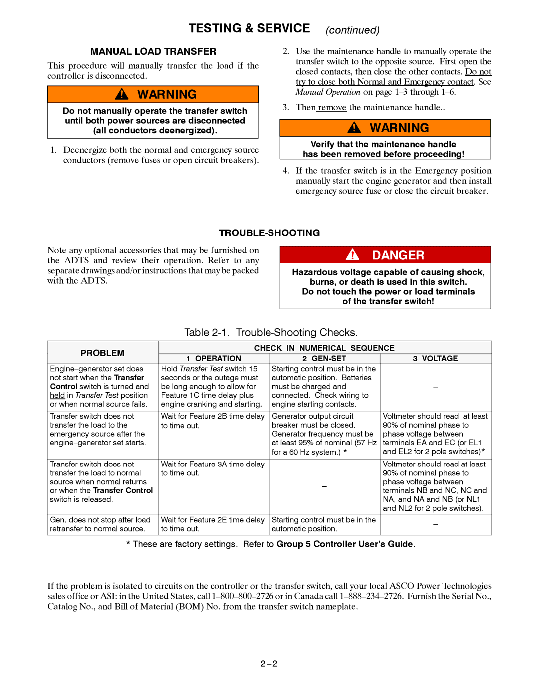
Table 2-1. Trouble-Shooting Checks.
PROBLEM | CHECK IN NUMERICAL SEQUENCE | |||
1 OPERATION | 2 | 3 VOLTAGE | ||
| ||||
Hold Transfer Test switch 15 | Starting control must be in the |
| ||
not start when the Transfer | seconds or the outage must | automatic position. Batteries |
| |
Control switch is turned and | be long enough to allow for | must be charged and | ||
held in Transfer Test position | Feature 1C time delay plus | connected. Check wiring to |
| |
or when normal source fails. | engine cranking and starting. | engine starting contacts. |
| |
|
|
|
| |
Transfer switch does not | Wait for Feature 2B time delay | Generator output circuit | Voltmeter should read at least | |
transfer the load to the | to time out. | breaker must be closed. | 90% of nominal phase to | |
emergency source after the |
| Generator frequency must be | phase voltage between | |
| at least 95% of nominal (57 Hz | terminals EA and EC (or EL1 | ||
|
| for a 60 Hz system.) * | and EL2 for 2 pole switches)* | |
|
|
|
| |
Transfer switch does not | Wait for Feature 3A time delay |
| Voltmeter should read at least | |
transfer the load to normal | to time out. |
| 90% of nominal phase to | |
source when normal returns |
| phase voltage between | ||
or when the Transfer Control |
| terminals NB and NC, NC and | ||
|
| |||
switch is released. |
|
| NA, and NA and NB (or NL1 | |
|
|
| and NL2 for 2 pole switches). | |
|
|
|
| |
Gen. does not stop after load | Wait for Feature 2E time delay | Starting control must be in the | ||
retransfer to normal source. | to time out. | automatic position. | ||
| ||||
|
|
|
| |
* These are factory settings. Refer to Group 5 Controller User’s Guide.
If the problem is isolated to circuits on the controller or the transfer switch, call your local ASCO Power Technologies sales office or ASI: in the United States, call
2 |