INSTALLATION (continued)
Do not manually operate the transfer switch until both power sources are disconnected: open both circuit breakers.
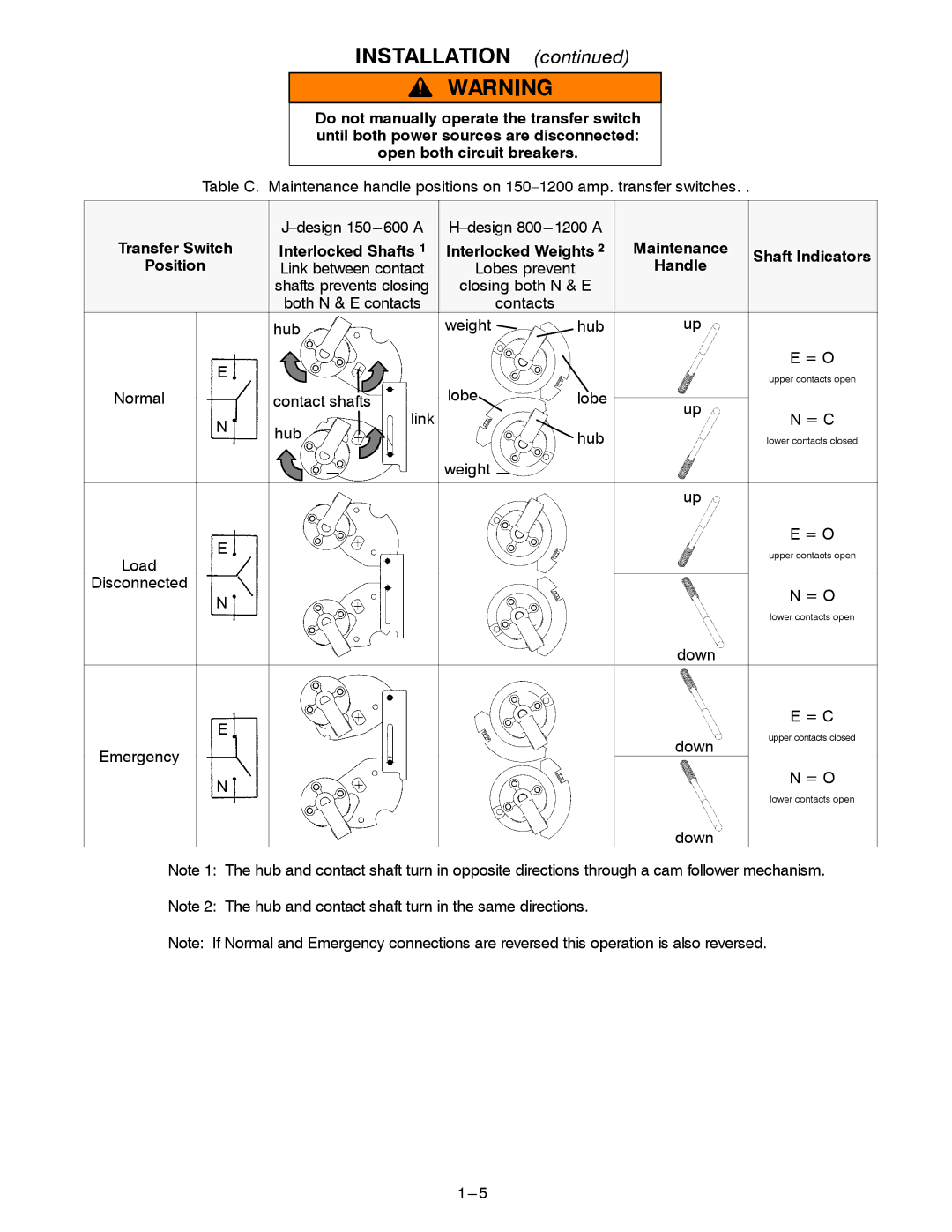
Table C. Maintenance handle positions on
|
|
| |||
Transfer Switch | Interlocked Shafts 1 | Interlocked Weights 2 | Maintenance | Shaft Indicators | |
Position | Link between contact | Lobes prevent |
| Handle | |
|
| ||||
| shafts prevents closing | closing both N & E |
|
| |
| both N & E contacts | contacts |
|
|
|
| hub | weight | hub | up |
|
E |
|
|
|
| E = O |
|
|
|
| upper contacts open | |
|
|
|
|
| |
Normal | t | lobe | lobe | up |
|
| contact shafts |
|
|
| |
N | link |
|
|
| N = C |
hub |
| hub |
| lower contacts closed | |
|
|
| |||
|
|
|
| ||
|
| weight |
|
|
|
|
|
|
| up |
|
E |
|
|
|
| E = O |
|
|
|
| upper contacts open | |
Load |
|
|
|
| |
|
|
|
|
| |
Disconnected |
|
|
|
| N = O |
N |
|
|
|
| |
|
|
|
| lower contacts open | |
|
|
|
|
| |
|
|
|
| down |
|
E |
|
|
|
| E = C |
|
|
| down | upper contacts closed | |
|
|
|
| ||
Emergency |
|
|
|
| |
|
|
|
|
| |
N |
|
|
|
| N = O |
|
|
|
| lower contacts open | |
|
|
|
|
| |
|
|
|
| down |
|
Note 1: The hub and contact shaft turn in opposite directions through a cam follower mechanism.
Note 2: The hub and contact shaft turn in the same directions.
Note: If Normal and Emergency connections are reversed this operation is also reversed.