INSTALLATION (continued)
Functional Test
The Functional Test consists of three checks:
❐1 — Manual Operation Test, pages
❐2 — Voltage Checks, page
❐3 — Electrical Operation, page
Do these checks in the order presented
to avoid damaging the ATS.
Read all instructions on the Wiring Diagram and labels affixed to the ATS. Note the control features that are provided and review their operation before proceeding.
Continue to 1 – Manual Operation Test starting below.
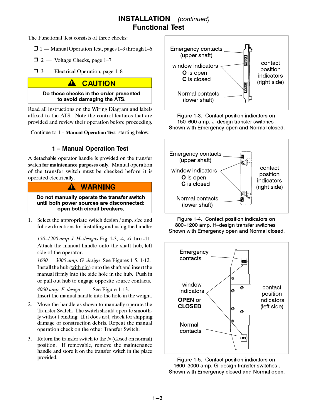
Emergency contacts (upper shaft) ![]()
window indicators | contact | |
position | ||
O is open | ||
indicators | ||
C is closed | ||
(right side) | ||
| ||
Normal contacts |
| |
(lower shaft) |
|
Figure 1-3. Contact position indicators on 150–600 amp. J–design transfer switches .
Shown with Emergency open and Normal closed.
1 – Manual Operation Test
A detachable operator handle is provided on the transfer switch for maintenance purposes only. Manual operation of the transfer switch must be checked before it is operated electrically.
Do not manually operate the transfer switch until both power sources are disconnected: open both circuit breakers.
1.Select the appropriate switch design / amp. size and follow directions for installing and using the handle:
1600 – 3000 amp.
4000 amp.
Insert the manual handle into the hole in the weight.
2.Move the handle as shown to manually operate the Transfer Switch. The switch should operate smooth- ly without binding. If it does not, check for shipping damage or construction debris. Repeat the manual operation check on the other Transfer Switch.
3.Return the transfer switch to the N (closed on normal) position. If removable, remove the maintenance handle and store it on the transfer switch in the place provided.
Emergency contacts (upper shaft) ![]()
window indicators | contact | |
position | ||
O is open | ||
indicators | ||
C is closed | ||
(right side) | ||
| ||
Normal contacts |
| |
(lower shaft) |
|
Figure 1-4. Contact position indicators on 800–1200 amp. H–design transfer switches . Shown with Emergency open and Normal closed.
Emergency contacts
window | contact | |
indicators | ||
position | ||
OPEN or | ||
indicators | ||
CLOSED | (left side) | |
Normal |
| |
contacts |
|