INSTALLATION (continued)
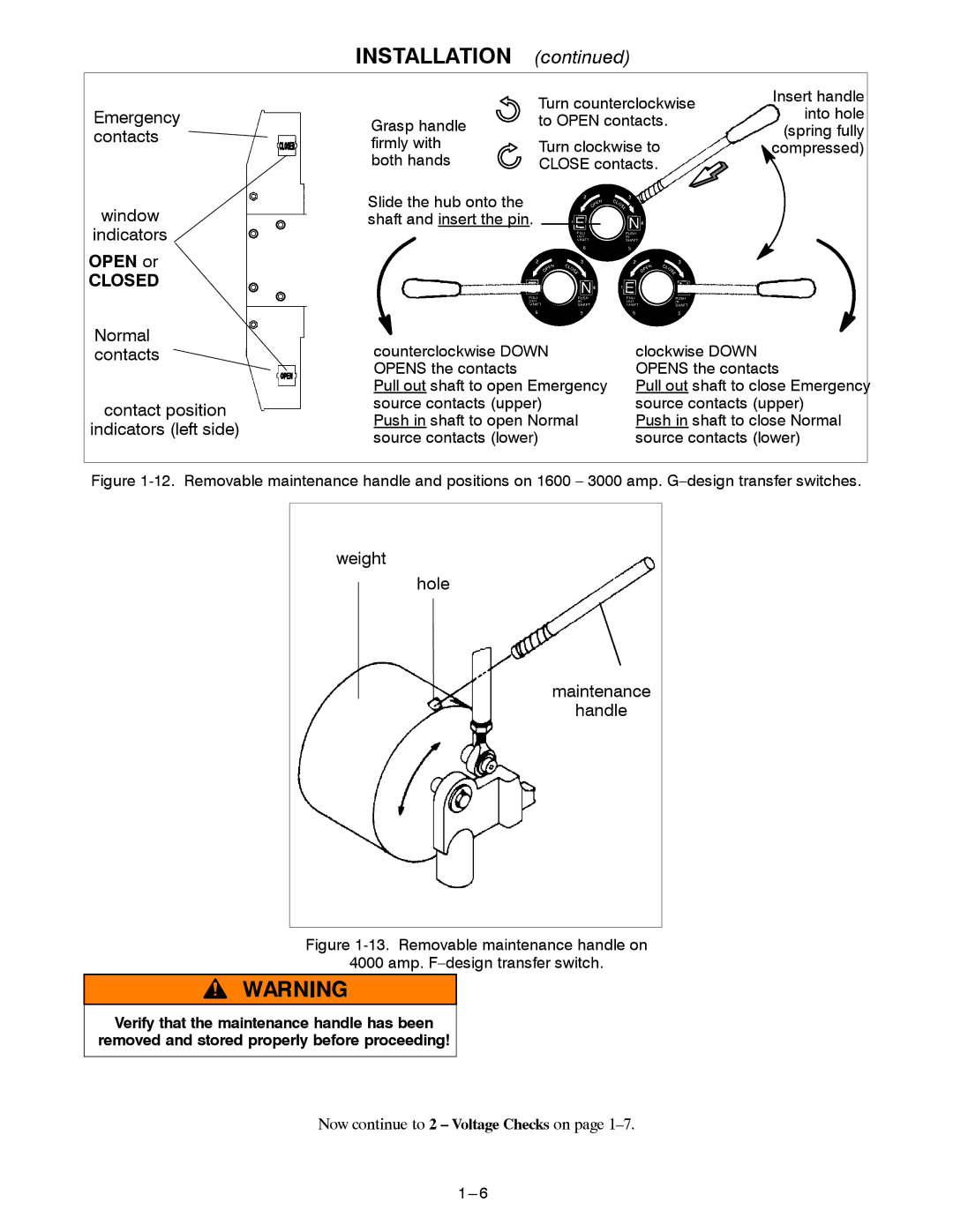
Emergency contacts
window
indicators
OPEN or
CLOSED
Grasp handle firmly with both hands
Slide the hub onto the shaft and insert the pin.
Turn counterclockwise | Insert handle | |
into hole | ||
to OPEN contacts. | ||
(spring fully | ||
Turn clockwise to | ||
compressed) | ||
CLOSE contacts. |
|
Normal contacts
contact position
indicators (left side)
counterclockwise DOWN | clockwise DOWN |
OPENS the contacts | OPENS the contacts |
Pull out shaft to open Emergency | Pull out shaft to close Emergency |
source contacts (upper) | source contacts (upper) |
Push in shaft to open Normal | Push in shaft to close Normal |
source contacts (lower) | source contacts (lower) |
Figure 1-12. Removable maintenance handle and positions on 1600 – 3000 amp. G–design transfer switches.
weight
hole
maintenance
handle
Figure 1-13. Removable maintenance handle on
4000 amp. F–design transfer switch.
Verify that the maintenance handle has been removed and stored properly before proceeding!
Now continue to 2 – Voltage Checks on page