INSTALLATION (continued)
Controller Ground
A grounding wire must be connected to the controller’s lower left mounting stud. Because the controller is mounted on the enclosure door, a conductive strap must be used between the enclosure and the door. This connection provides proper grounding which does not rely upon the door hinges.
Harnesses
The transfer switch is connected to the left side of the control panel by a
Auxiliary Circuits
Connect auxiliary circuit wires to appropriate terminals on the transfer switch. Note the control features that are furnished on this switch. Make the necessary auxiliary connections by referring to the Wiring Diagram.
Engine Starting Contacts
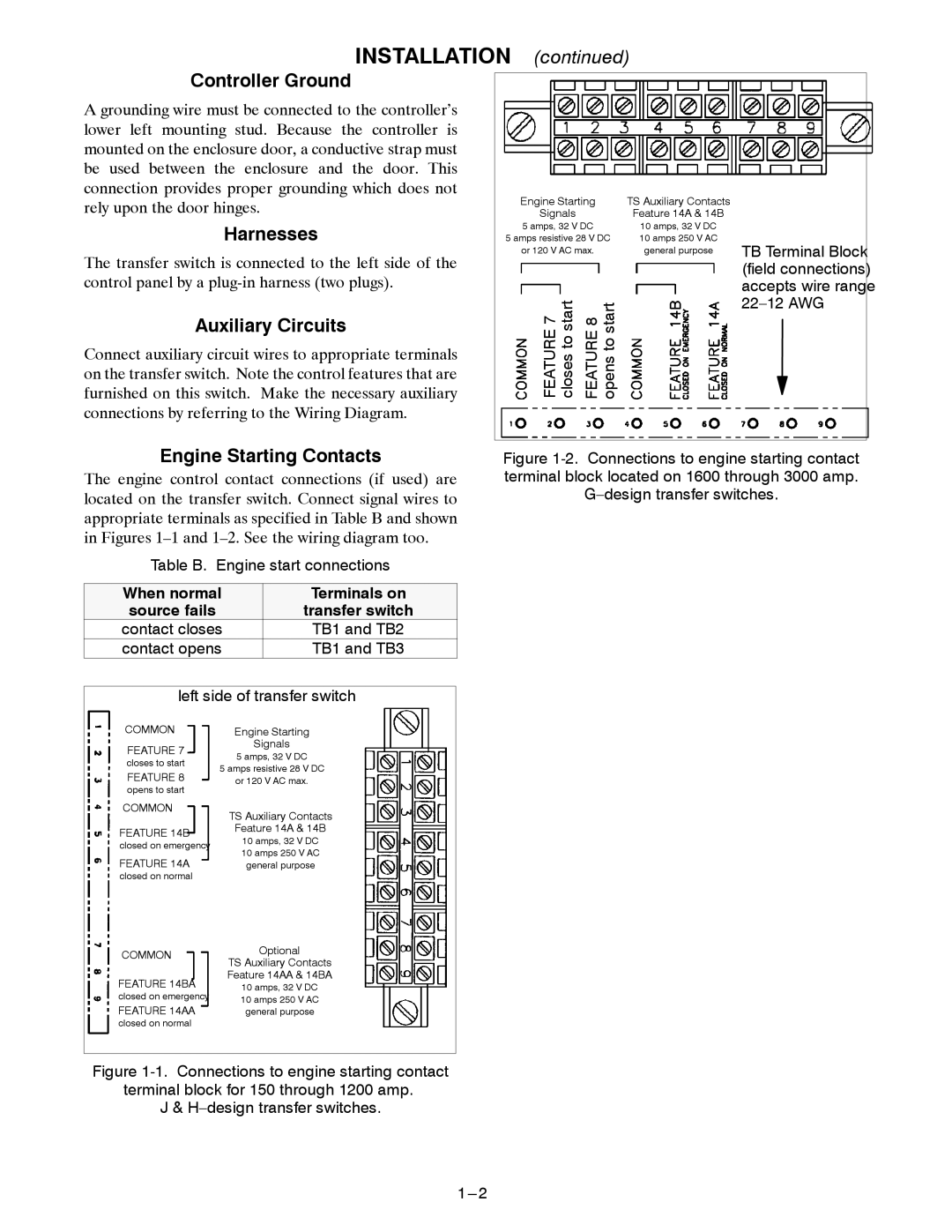
The engine control contact connections (if used) are located on the transfer switch. Connect signal wires to appropriate terminals as specified in Table B and shown in Figures
Table B. Engine start connections
When normal |
| Terminals on | |||
source fails |
|
| transfer switch | ||
contact closes |
| TB1 and TB2 | |||
contact opens |
| TB1 and TB3 | |||
| |||||
left side of transfer switch |
| ||||
COMMON |
| Engine Starting | |||
FEATURE 7 |
| Signals | |||
| 5 amps, 32 V DC | ||||
closes to start |
| ||||
5 amps resistive 28 V DC | |||||
FEATURE 8 | |||||
| or 120 V AC max. | ||||
opens to start |
|
|
|
| |
COMMON |
| TS Auxiliary Contacts | |||
|
| ||||
FEATURE 14B |
| Feature 14A & 14B | |||
| 10 amps, 32 V DC | ||||
closed on emergency |
| ||||
| 10 amps 250 V AC | ||||
FEATURE 14A |
| ||||
| general purpose | ||||
closed on normal |
|
|
|
| |
COMMON |
| Optional | |||
| TS Auxiliary Contacts | ||||
|
| ||||
FEATURE 14BA |
| Feature 14AA & 14BA | |||
| 10 amps, 32 V DC | ||||
closed on emergency |
| 10 amps 250 V AC | |||
FEATURE 14AA |
| ||||
| general purpose | ||||
closed on normal
Figure 1-1. Connections to engine starting contact terminal block for 150 through 1200 amp.
J & H–design transfer switches.
Engine Starting | TS Auxiliary Contacts |
|
|
Signals | Feature 14A & 14B |
|
|
5 amps, 32 V DC | 10 amps, 32 V DC |
|
|
5 amps resistive 28 V DC | 10 amps 250 V AC | TB Terminal Block |
|
or 120 V AC max. | general purpose |
| |
|
| (field connections) |
|
|
| accepts wire range |
|
FEATURE 7 closes to start FEATURE 8 opens to start |
|
| |
|
|
| |
|
|
|
|
