
CF3300ORH, CF3300AP specifications
The Emerson CF3300 series boasts two remarkable ceiling fans, the CF3300AP and the CF3300ORH, both engineered to provide an optimal blend of style, functionality, and energy efficiency. These fans are designed for residential and commercial settings, making them versatile choices for a variety of environments.One of the most notable features of the CF3300AP is its sophisticated design. It comes in a polished aluminum finish that adds a touch of elegance to any space. The CF3300ORH, on the other hand, sports a rich oil-rubbed bronze finish, giving it a more traditional feel. Both models are aesthetically pleasing and fit well within various decor styles, from modern to classic.
In terms of functionality, these ceiling fans are equipped with powerful yet efficient motors. The DC motor technology employed in the CF3300 series ensures a quiet operation, allowing users to enjoy the cooling breeze without disruptive noise. The fans also come with multiple speed settings that enable users to customize airflow according to their preference.
Energy efficiency is another hallmark of the Emerson CF3300 models. Designed with sustainability in mind, these fans consume significantly less electricity compared to traditional ceiling fans, making them an eco-friendly option. This not only reduces the carbon footprint but also leads to lower energy bills, appealing to environmentally conscious consumers.
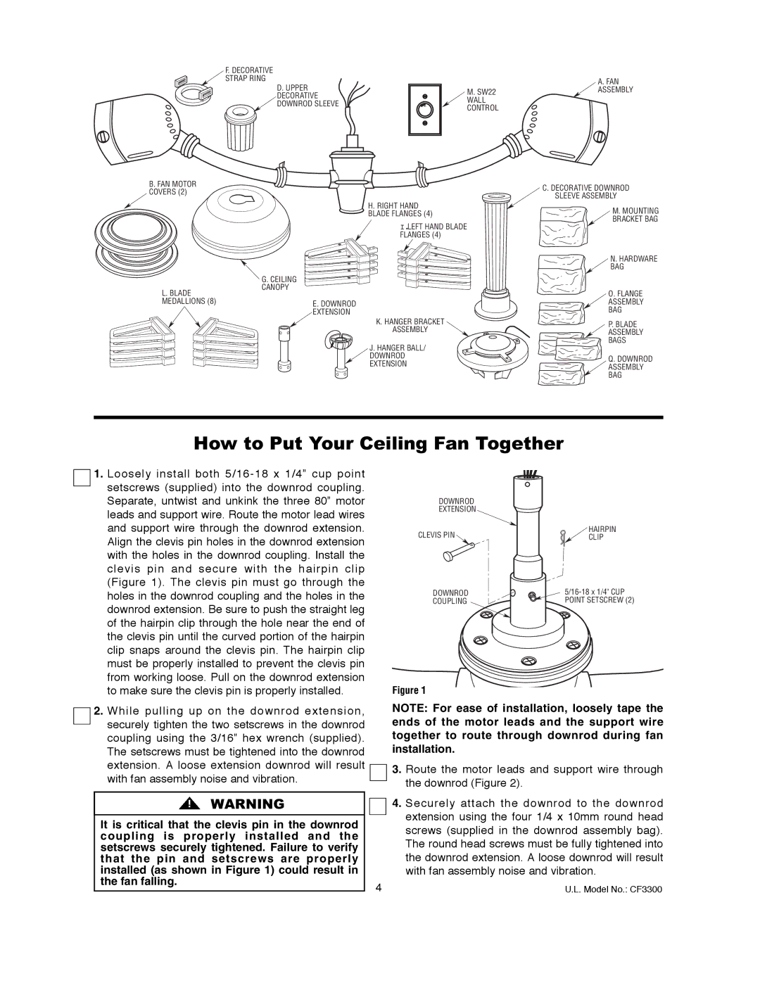
Installation of both the CF3300AP and CF3300ORH is made simple with their user-friendly design. They come with a comprehensive Installation Guide, allowing DIY enthusiasts to set them up with ease. For those who prefer professional installation, the fans are compatible with standard ceiling mounting systems.
Another standout feature is the incorporation of advanced airflow technologies. The fans are designed with large blades that maximize air circulation, providing a refreshing breeze throughout the entire space. Additionally, their reverse function allows for year-round use by pushing warm air down during winter months, making them a versatile solution for climate control.
The Emerson CF3300 series also offers remote control capabilities, providing convenience for adjusting fan speeds and settings from anywhere in the room. This modern feature allows users to avoid leaving their seats, enhancing comfort and usability.
In summary, the Emerson CF3300AP and CF3300ORH ceiling fans blend elegant aesthetics with advanced technology, energy efficiency, and user-friendliness. Ideal for a variety of settings, these fans promise to enhance comfort while providing stylish solutions for indoor air circulation. With their robust features and designs, the CF3300 series continues to stand out in the market of ceiling fans.