BP7315 Florissant 3/7/06 8:42 AM Page 8
![]()
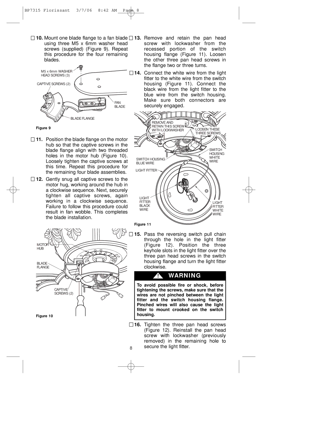
![]() 10. Mount one blade flange to a fan blade using three M5 x 6mm washer head screws (supplied) (Figure 9). Repeat this procedure for the four remaining blades.
10. Mount one blade flange to a fan blade using three M5 x 6mm washer head screws (supplied) (Figure 9). Repeat this procedure for the four remaining blades.
M5 x 6mm WASHER
HEAD SCREWS (3)
CAPTIVE SCREWS (2)
FAN
BLADE
 BLADE FLANGE
Figure 9
![]()
![]() 13. Remove and retain the pan head screw with lockwasher from the recessed portion of the switch housing flange (Figure 11). Loosen the other three pan head screws in the flange two or three turns.
13. Remove and retain the pan head screw with lockwasher from the recessed portion of the switch housing flange (Figure 11). Loosen the other three pan head screws in the flange two or three turns.
![]()
![]() 14. Connect the white wire from the light fitter to the white wire from the switch housing (Figure 11). Connect the black wire from the light fitter to the blue wire from the switch housing. Make sure both connectors are securely engaged.
14. Connect the white wire from the light fitter to the white wire from the switch housing (Figure 11). Connect the black wire from the light fitter to the blue wire from the switch housing. Make sure both connectors are securely engaged.
REMOVE AND |
|
RETAIN THIS SCREW | LOOSEN THESE |
WITH LOCKWASHER | |
| THREE SCREWS |
![]()
![]() 11. Position the blade flange on the motor hub so that the captive screws in the blade flange align with two threaded holes in the motor hub (Figure 10). Loosely tighten the captive screws at this time. Repeat this procedure for the remaining four blade assemblies.
11. Position the blade flange on the motor hub so that the captive screws in the blade flange align with two threaded holes in the motor hub (Figure 10). Loosely tighten the captive screws at this time. Repeat this procedure for the remaining four blade assemblies.
12. Gently snug all captive screws to the motor hug, working around the hub in a clockwise sequence. Next, securely tighten all captive screws, again working in a clockwise sequence. Failure to follow this procedure could result in fan wobble. This completes the blade installation.
| SWITCH | |
| HOUSING | |
SWITCH HOUSING | WHITE | |
WIRE | ||
BLUE WIRE | ||
| ||
LIGHT FITTER |
|
LIGHT |
|
FITTER | LIGHT |
BLACK | FITTER |
WIRE | WHITE |
| WIRE |
Figure 11
MOTOR HUB
BLADE FLANGE
![]()
![]() 15. Pass the reversing switch pull chain through the hole in the light fitter (Figure 12). Position the three keyhole slots in the light fitter over the three pan head screws in the switch housing flange and turn the light fitter clockwise.
15. Pass the reversing switch pull chain through the hole in the light fitter (Figure 12). Position the three keyhole slots in the light fitter over the three pan head screws in the switch housing flange and turn the light fitter clockwise.
! WARNING
CAPTIVE
SCREWS (2)
Figure 10
To avoid possible fire or shock, before tightening the screws, make sure that the wires are not pinched between the light fitter and the switch housing flange. Pinched wires will also cause the light fitter to mount crooked on the switch housing.
![]()
![]() 16. Tighten the three pan head screws (Figure 12). Reinstall the pan head screw with lockwasher (previously removed) in the remaining hole to
16. Tighten the three pan head screws (Figure 12). Reinstall the pan head screw with lockwasher (previously removed) in the remaining hole to
8secure the light fitter.