BP7315 Florissant 3/7/06 8:42 AM Page 10
Installation of Wall
Control
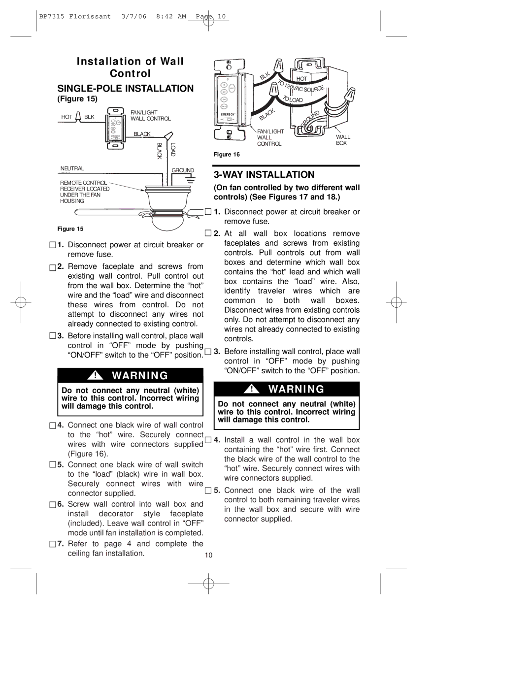
SINGLE-POLE INSTALLATION
(Figure 15)
HOT | BLK | FAN/LIGHT |
|
WALL CONTROL |
| ||
| EMERSON | BLACK |
|
|
| BLACK | LOAD |
NEUTRAL |
|
| GROUND |
|
|
| |
REMOTE CONTROL |
|
| |
RECEIVER LOCATED |
|
| |
UNDER THE FAN |
|
| |
HOUSING |
|
|
|
HI |
|
|
| LIGHT |
|
MED |
|
|
LOW |
|
|
FAN OFF |
|
|
EMERSON | ® | |
| ||
OFF | ON |
|
BLK | T |
|
| HOT |
|
|
| |
| O |
|
|
|
|
|
|
|
| 1 | 2 | 0V |
|
| O |
| E |
|
|
|
|
| ||||
|
|
| AC | S | C | |||
|
|
|
|
| UR |
| ||
T |
|
| |
BLACK | O LOAD |
|
|
|
| D | |
|
|
| N |
|
|
| U |
| G | R | O |
|
| ||
FAN/LIGHT |
|
| |
|
| WALL | |
WALL |
|
| |
CONTROL |
|
| BOX |
Figure 15
![]()
![]() 1. Disconnect power at circuit breaker or remove fuse.
1. Disconnect power at circuit breaker or remove fuse.
![]()
![]() 2. Remove faceplate and screws from existing wall control. Pull control out from the wall box. Determine the “hot” wire and the “load” wire and disconnect these wires from control. Do not attempt to disconnect any wires not already connected to existing control.
2. Remove faceplate and screws from existing wall control. Pull control out from the wall box. Determine the “hot” wire and the “load” wire and disconnect these wires from control. Do not attempt to disconnect any wires not already connected to existing control.
3. Before installing wall control, place wall control in “OFF” mode by pushing “ON/OFF” switch to the “OFF” position. 3.
!WARNING
Before installing wall control, place wall control in “OFF” mode by pushing “ON/OFF” switch to the “OFF” position.
Do not connect any neutral (white) wire to this control. Incorrect wiring will damage this control.
4. | Connect one black wire of wall control | |
| to the “hot” wire. Securely connect | |
| wires with wire connectors supplied | |
| (Figure 16). |
|
5. | Connect one black wire of wall switch | |
| to the “load” (black) wire in wall box. | |
| Securely connect wires with wire | |
| connector supplied. |
|
6. | Screw wall control into wall box and | |
| install decorator style | faceplate |
| (included). Leave wall control in “OFF” | |
| mode until fan installation is completed. | |
7. | Refer to page 4 and complete the | |
| ceiling fan installation. | 10 |
!WARNING
Do not connect any neutral (white) wire to this control. Incorrect wiring will damage this control.
4.Install a wall control in the wall box containing the “hot” wire first. Connect the black wire of the wall control to the “hot” wire. Securely connect wires with wire connectors supplied.
5.Connect one black wire of the wall control to both remaining traveler wires in the wall box and secure with wire connector supplied.