BP7315 Florissant 3/7/06 8:42 AM Page 9
NOTE: Make sure that the lockwashers are positioned between the screw head and the light fitter.
| HOLE |
CLIP | CHAIN |
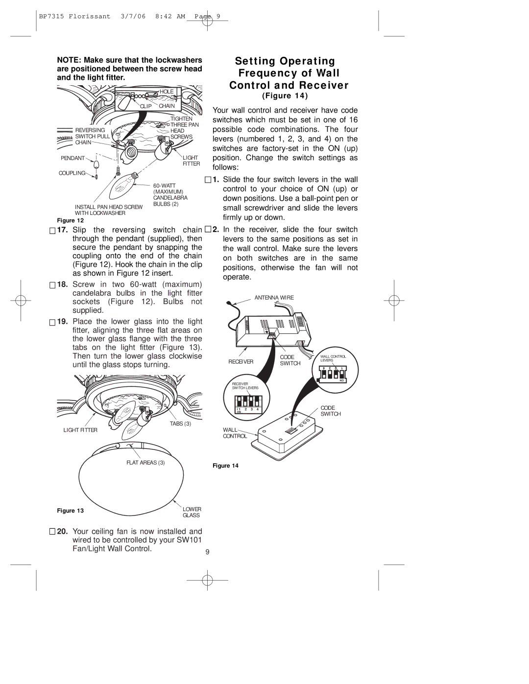
Setting Operating
Frequency of Wall
Control and Receiver
(Figure 14)
Your wall control and receiver have code
REVERSING SWITCH PULL ![]() CHAIN
CHAIN ![]()
![]()
![]()
PENDANT ![]()
COUPLING![]()
INSTALL PAN HEAD SCREW WITH LOCKWASHER
Figure 12
TIGHTEN
THREE PAN
HEAD
SCREWS
LIGHT
FITTER
CANDELABRA BULBS (2)
switches which must be set in one of 16 possible code combinations. The four levers (numbered 1, 2, 3, and 4) on the switches are
![]()
![]() 1. Slide the four switch levers in the wall control to your choice of ON (up) or down positions. Use a
1. Slide the four switch levers in the wall control to your choice of ON (up) or down positions. Use a
![]()
![]() 17. Slip the reversing switch chain
17. Slip the reversing switch chain ![]() through the pendant (supplied), then secure the pendant by snapping the coupling onto the end of the chain (Figure 12). Hook the chain in the clip as shown in Figure 12 insert.
through the pendant (supplied), then secure the pendant by snapping the coupling onto the end of the chain (Figure 12). Hook the chain in the clip as shown in Figure 12 insert.
![]()
![]() 18. Screw in two
18. Screw in two
![]()
![]() 19. Place the lower glass into the light fitter, aligning the three flat areas on the lower glass flange with the three tabs on the light fitter (Figure 13). Then turn the lower glass clockwise until the glass stops turning.
19. Place the lower glass into the light fitter, aligning the three flat areas on the lower glass flange with the three tabs on the light fitter (Figure 13). Then turn the lower glass clockwise until the glass stops turning.
2.In the receiver, slide the four switch levers to the same positions as set in the wall control. Make sure the levers on both switches are in the same positions, otherwise the fan will not operate.
ANTENNA WIRE
ON
RECEIVER | CODE | WALL CONTROL | ||||
SWITCH | LEVERS |
|
| |||
4 | 3 | 2 | 1 | |||
|
| |||||
![]()
![]()
![]() TABS (3) LIGHT FITTER
TABS (3) LIGHT FITTER
ON
RECEIVER
SWITCH LEVERS
1 | 2 | 3 | 4 | CODE |
ON |
|
|
| SWITCH |
|
|
|
| |
WALL |
|
|
|
|
CONTROL |
|
|
| |
FLAT AREAS (3) | Figure 14 |
|
Figure 13 | LOWER |
| GLASS |
![]()
![]() 20. Your ceiling fan is now installed and wired to be controlled by your SW101
20. Your ceiling fan is now installed and wired to be controlled by your SW101
Fan/Light Wall Control. | 9 |
|