BP7315 Florissant 3/7/06 8:42 AM Page 11
NOTE: Retrofit
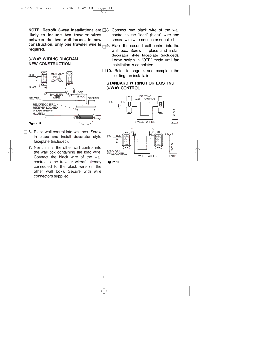
3-WAY WIRlNG DIAGRAM: NEW CONSTRUCTION
![]()
![]() 8. Connect one black wire of the wall control to the “load” (black) wire and secure with wire connector supplied.
8. Connect one black wire of the wall control to the “load” (black) wire and secure with wire connector supplied.
![]()
![]() 9. Place the second wall control into the wall box. Screw in place and install decorator style faceplate (included).
9. Place the second wall control into the wall box. Screw in place and install decorator style faceplate (included).
Leave switch in “OFF” mode until fan installation is completed.
HOT |
| FAN/LIGHT |
|
|
| WALL |
|
| EMERSON | CONTROL | EMERSON |
BLACK |
| BLK | BLK |
|
| ||
|
| TRAVELER |
|
NEUTRAL |
| WIRE |
|
REMOTE CONTROL
RECEIVER LOCATED
UNDER THE FAN
HOUSING
![]()
![]() 10. Refer to page 4 and complete the ceiling fan installation.
10. Refer to page 4 and complete the ceiling fan installation.
STANDARD WIRING FOR EXISTING 3-WAY CONTROL
LOAD |
|
|
BLACK | GROUND | EXISTING |
| WALL CONTROL | |
| HOT | BLK |
BLACK
Figure 17
![]()
![]() 6. Place wall control into wall box. Screw in place and install decorator style faceplate (included).
6. Place wall control into wall box. Screw in place and install decorator style faceplate (included).
![]()
![]() 7. Next, install the other wall control into the wall box containing the load wire. Connect the black wire of the wall control to the traveler wire(s) already connected to the black wire (in the other wall box). Secure with wire connectors supplied.
7. Next, install the other wall control into the wall box containing the load wire. Connect the black wire of the wall control to the traveler wire(s) already connected to the black wire (in the other wall box). Secure with wire connectors supplied.
TRAVELER WIRES |
| LOAD | |
|
|
| |
BLK | BLK |
| BLK |
HOT BLK |
|
| |
|
|
| |
EMERSON |
| EMERSON | BLACK |
FAN/LIGHT |
|
| |
|
|
| |
WALL CONTROL | TRAVELER WIRES |
| LOAD |
|
| ||
Figure 18
11