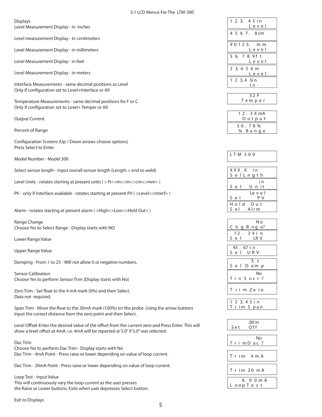
5.1 LCD Menus For The LTM-300
Displays
Level Measurement Display - in inches
Level measurement Display - in centimeters
Level Measurement Display - in millimeters
Level Measurement Display - in feet
Level Measurement Display - in meters
Interface Measurements - same decimal positions as Level
Only if configuration set to Level+Interface or All
Temperature Measurements - same decimal positions for F or C
Only if configuration set to Level+ Temper or All
Output Current
Percent of Range
Configuration Screens (Up / Down arrows choose options)
Press Select to Enter.
Model Number - Model 300
Select sensor length - Input overall sensor length (Length = end to weld)
Level Units - rotates starting at present units ( > ft<>m<>in<>cm<>mm> )
PV - only if Interface available - rotates starting at present PV ( >Level<>Interf> )
Alarm - rotates starting at present alarm ( >High<>Low<>Hold Out> )
Range Change
Choose Yes to Select Range - Display starts with NO
Lower Range Value
Upper Range Value
Damping - From 1 to 25 - Will not allow 0 or negative numbers.
Sensor Calibration
Choose Yes to perform Sensor Trim (Display starts with No)
Zero Trim - Set float to the 4 mA mark (0%) and then Select.
Data not required.
Span Trim - Move the float to the 20mA mark (100%) on the probe. Using the arrow buttons input the correct distance from the zero point and then Select.
Level
Dac Trim
Choose Yes to perform Dac Trim - Display starts with No
Dac Trim - 4mA Point - Press raise or lower depending on value of loop current.
Dac Trim - 20mA Point - Press raise or lower depending on value of loop current.
Loop Test - Input Value
This will continuously vary the loop current as the user presses
the Raise or Lower buttons. Exits when user depresses Select button.
Exit to Displays
5
1 | 2 | 3. | 4 5 i n | |
|
|
| L e v e l | |
|
|
|
|
|
4 | 5 | 6 7 . 8 cm | ||
|
| |||
|
| |||
9 0 1 2 3. | m m | |||
|
|
| L e v e l | |
|
|
|
|
|
5 | 6. | 7 | 8 | 9 f t |
|
|
| L e v e l | |
|
|
|
| |
2 | 3. 4 | 5 | 6 m | |
|
|
| L e v e l | |
|
|
|
|
|
1 | 2 | 3. 4 | 5i n | |
|
|
|
| I n - |
|
|
|
| |
|
|
| 3 2 F | |
|
| T e m p e r | ||
|
| |||
| 1 2 . 3 4 mA | |||
|
| O u t p u t | ||
|
| |||
| 5 6 . 7 8 % | |||
| % | R a n g e | ||
L T M 3 0 0
X X X . X | I n | ||
S | e | l L n g t h | |
|
|
|
|
|
|
| i n |
S | e | l | U n i t |
|
|
| Le v e l |
S | e l | P V | |
H o l d | O u t | ||
S | e l |
| A l r m |
|
|
|
|
|
|
| N o |
C h g R n g e?
| 1 2 . |
| 3 4 i n | ||
S | e | l |
| LR V | |
|
|
|
| ||
| 45 . | 67 i n |
| ||
S | e | l |
| U R V | |
|
|
|
|
|
|
|
|
|
| 3. | s |
S e l | D a m p | ||||
|
|
|
|
|
|
|
|
|
|
| No |
T | r | n | S | n s | r ? |
|
|
|
|
| |
T | r i | m | Z e | r o | |
|
|
| |||
|
|
| |||
1 | 2 | 3. 4 5 i n | |||
T r | i m | S p a n | |||
|
|
|
|
| |
|
|
|
| .00 in | |
S e t |
| O f f | |||
|
|
|
|
|
|
|
|
|
|
| No |
T r i | m D a c ? | ||||
|
|
|
|
|
|
T r i m | 4 m A | ||||
|
|
|
|
|
|
Tr i m 2 0 m A
8.0 0 m A
L o o p T e s t
