Wiring Instructions
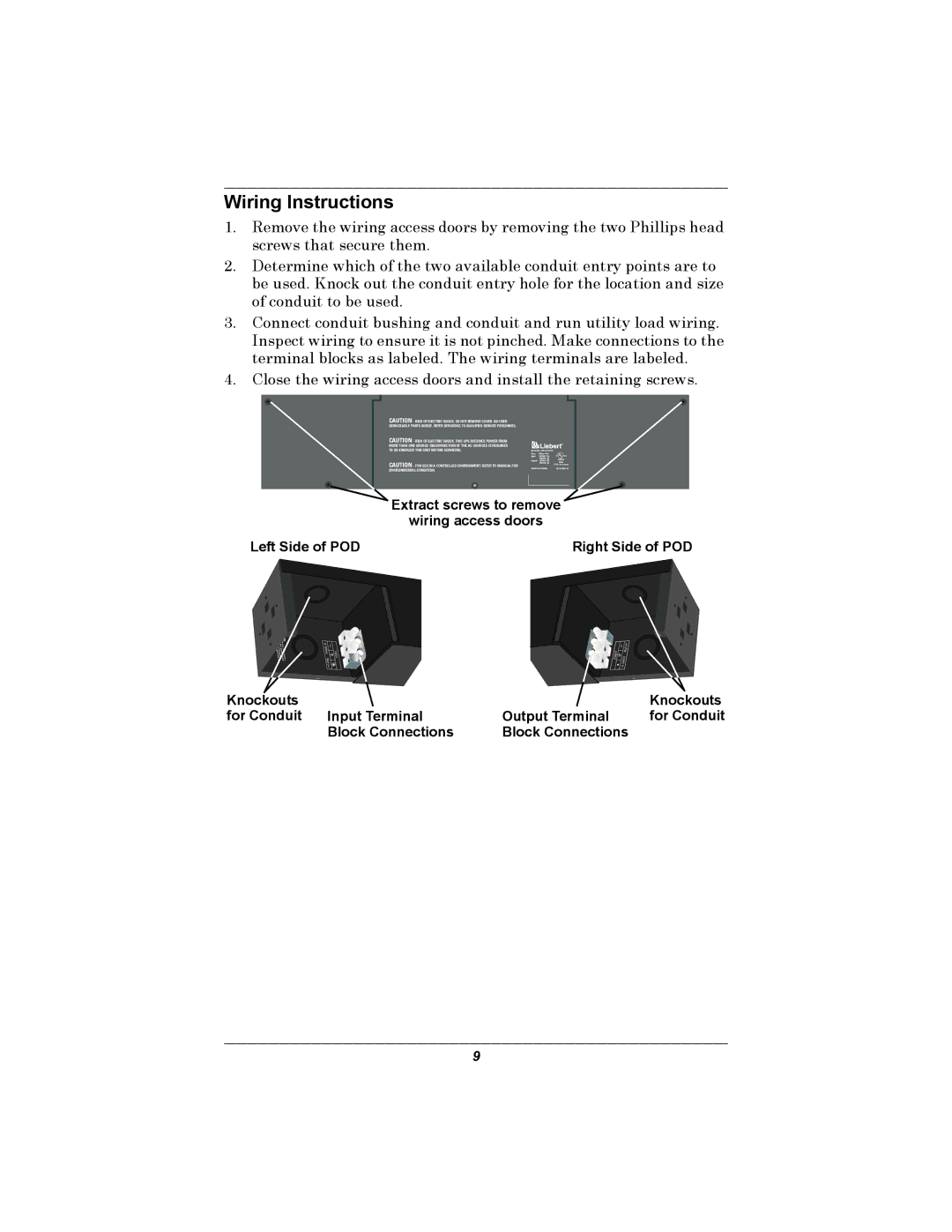
1.Remove the wiring access doors by removing the two Phillips head screws that secure them.
2.Determine which of the two available conduit entry points are to be used. Knock out the conduit entry hole for the location and size of conduit to be used.
3.Connect conduit bushing and conduit and run utility load wiring. Inspect wiring to ensure it is not pinched. Make connections to the terminal blocks as labeled. The wiring terminals are labeled.
4.Close the wiring access doors and install the retaining screws.
CAUTION - RISK OF ELECTRIC SHOCK, SO NOT REMOVE COVER. NO USER SERVICEABLE PARTS INSIDE. REFER SERVICING TO QUALIFIED SERVICE PERSONNEL.
CAUTION - RISK OF ELECTRIC SHOCK, THIS UPS RECEIVES POWER FROM MORE THAN ONE
CAUTION - FOR USE IN A CONTROLLED ENVIRONMENT. REFER TO MANUAL FOR ENVIRONMENTAL CONDITION.
Model No. : |
| |
Desc. | : Micro Pod | C UL US |
Input | : 120VAC 12A | |
| 50/60Hz, 10 | LISTED |
Ouptut | : 120VAC 12A | 91N6 |
| 50/60Hz, 10 | U.P.S. Accessory |
MADE IN TAIWAN | ||
Extract screws to remove
wiring access doors
Left Side of POD | Right Side of POD |
| wcircuit | CAUTION: | |
A |
| To |
|
NSI/N | branchcircuitreduce |
| |
FPAaccordance | the | ||
70. ith providedwrisk | |||
| overcurrent am |
| |
| the | ith of | |
| Nationa | 15fire, | |
| pe | ||
| lprote resconnect | ||
| Electricction | nly | |
|
|
| m o |
|
| inaxim toa | |
| Code | um | |
Knockouts for Conduit
14 |
| L |
- |
|
|
12AWG | NInput | |
|
| |
8Kgf | ||
| - | |
| cm | |
Input Terminal Block Connections
| L | m | |
| |||
|
|
| gf |
Output | N |
| 8K |
G | |||
|
| AW |
|
|
|
| |
|
| 14 |
|
Knockouts
Output Terminal for Conduit Block Connections
9
