APPLY FEED POWER
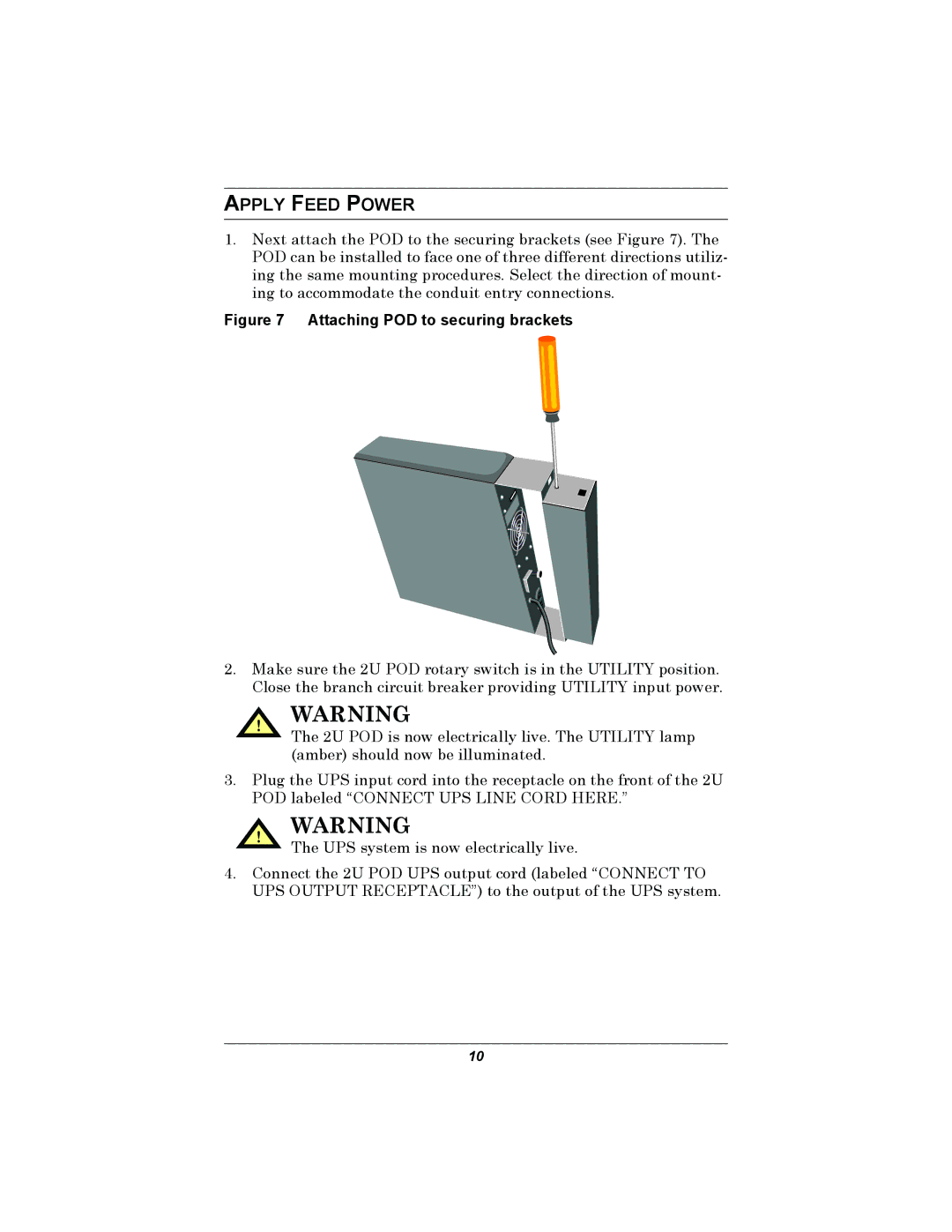
1.Next attach the POD to the securing brackets (see Figure 7). The POD can be installed to face one of three different directions utiliz- ing the same mounting procedures. Select the direction of mount- ing to accommodate the conduit entry connections.
Figure 7 Attaching POD to securing brackets
2.Make sure the 2U POD rotary switch is in the UTILITY position. Close the branch circuit breaker providing UTILITY input power.
! WARNING
The 2U POD is now electrically live. The UTILITY lamp (amber) should now be illuminated.
3.Plug the UPS input cord into the receptacle on the front of the 2U POD labeled “CONNECT UPS LINE CORD HERE.”
! WARNING
The UPS system is now electrically live.
4.Connect the 2U POD UPS output cord (labeled “CONNECT TO UPS OUTPUT RECEPTACLE”) to the output of the UPS system.
10