Installation, Operation & Maintenance Manual
IP262/Z0, Rev. AB
February 2012 | MSL600 |
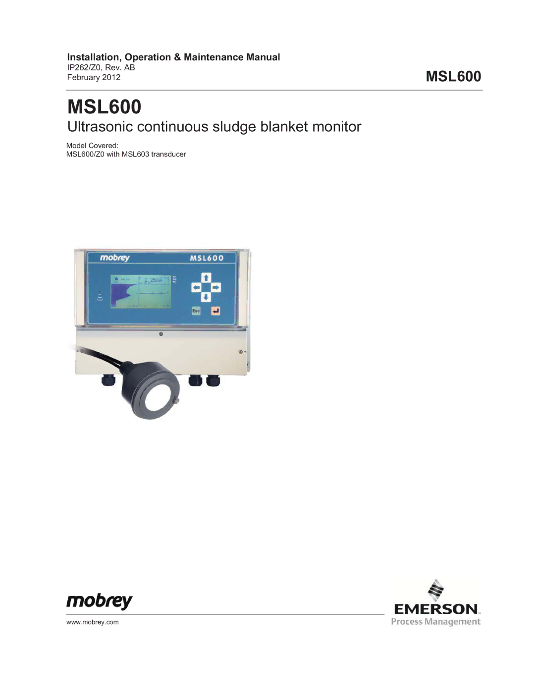
MSL600
Ultrasonic continuous sludge blanket monitor
Model Covered:
MSL600/Z0 with MSL603 transducer
www.mobrey.com
IP262/Z0, Rev. AB
February 2012 | MSL600 |
Model Covered:
MSL600/Z0 with MSL603 transducer
www.mobrey.com