ASSEMBLY OF STOVE CASTING (continued)
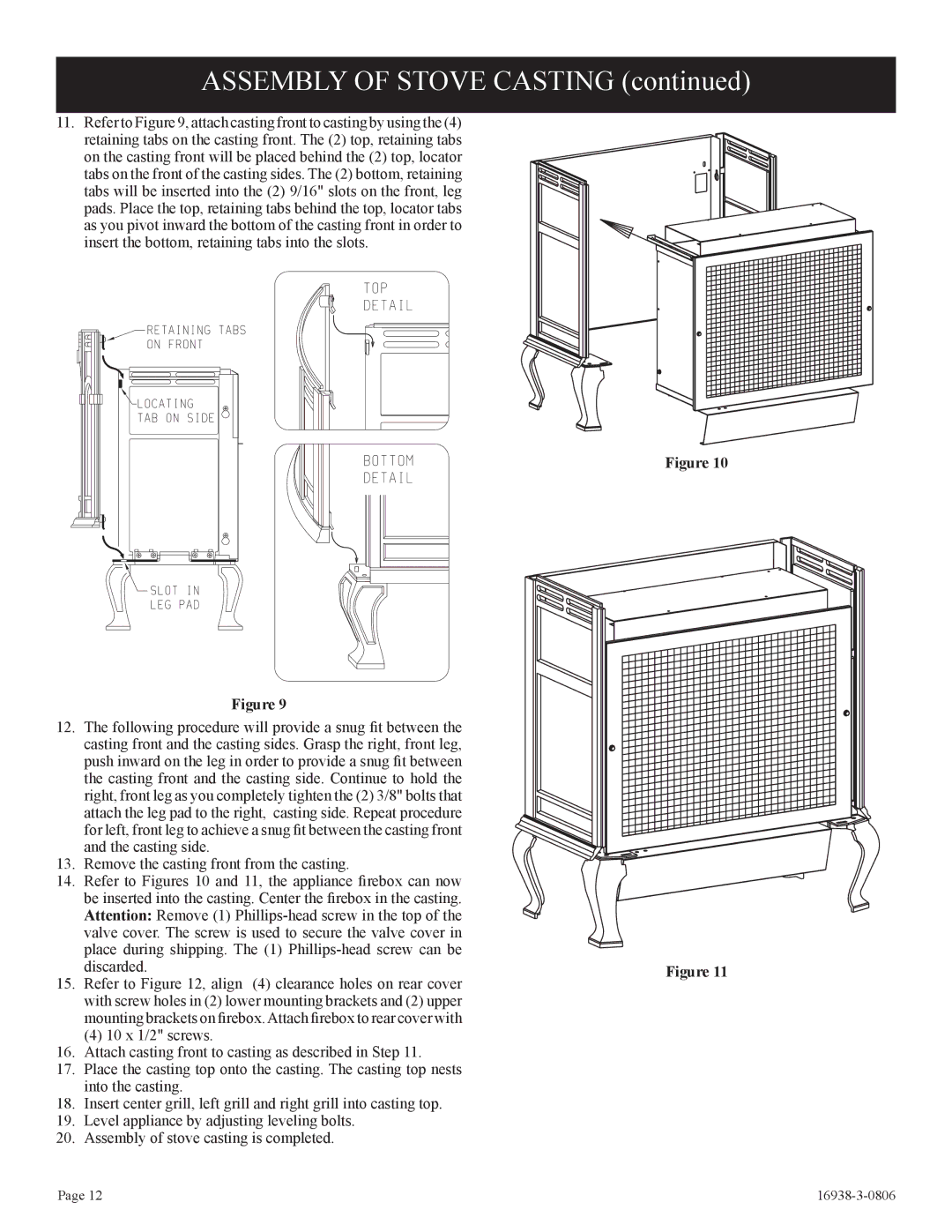
11.Refer to Figure 9, attach casting front to casting by using the (4) retaining tabs on the casting front. The (2) top, retaining tabs on the casting front will be placed behind the (2) top, locator tabs on the front of the casting sides. The (2) bottom, retaining tabs will be inserted into the (2) 9/16" slots on the front, leg pads. Place the top, retaining tabs behind the top, locator tabs as you pivot inward the bottom of the casting front in order to insert the bottom, retaining tabs into the slots.
Figure 9
12.The following procedure will provide a snug fit between the casting front and the casting sides. Grasp the right, front leg, push inward on the leg in order to provide a snug fit between the casting front and the casting side. Continue to hold the right, front leg as you completely tighten the (2) 3/8" bolts that attach the leg pad to the right, casting side. Repeat procedure for left, front leg to achieve a snug fit between the casting front and the casting side.
13.Remove the casting front from the casting.
14.Refer to Figures 10 and 11, the appliance firebox can now be inserted into the casting. Center the firebox in the casting. Attention: Remove (1)
15. Refer to Figure 12, align (4) clearance holes on rear cover with screw holes in (2) lower mounting brackets and (2) upper mounting brackets on firebox.Attach firebox to rear cover with
(4) 10 x 1/2" screws.
16. Attach casting front to casting as described in Step 11.
17. Place the casting top onto the casting. The casting top nests into the casting.
18. Insert center grill, left grill and right grill into casting top.
19.Level appliance by adjusting leveling bolts.
20.Assembly of stove casting is completed.
Figure 10
Figure 11
Page 12 |
|