OPTIONAL STONE INLAY INSTALLATION
Whenever the standard grill top is replaced with a stone inlay you must install the top shield and heat shield, which are provided with the stone inlay.
Installation of Optional Stone Inlay
1.Remove left grill, center grill and right grill from casting top.
2.Remove casting top from outer casting.
3.Place the casting top on a
4.Attach 11 5/8" x 11 5/8" top shield to the interior of the casting top with (1) 3/8" bolt provided in hardware package.
5.Locate the (4) screw holes on the heat exchanger top. The screw holes are 8 3/4" apart. Position the angled front edge on the 12" x 19 3/8" heat shield with the front of the firebox. Align the (4) tabs with clearance holes on the 12" x 19 3/8" heat shield with the (4) screw holes on the heat exchanger top. Attach the 12" x 19 3/8" heat shield to the heat exchanger top with (4) 1/2"
6.Place the casting top onto the casting. The casting top nests into the casting.
7.Insert center stone inlay, left stone inlay and right stone inlay into casting top.
8.Installation of stone inlay is completed.
Parts List
Part Description | Part | Quantity |
| Number | Supplied |
11 5/8" x 11 5/8" Top Shield | 1 | |
12" x 19 3/8" Heat Shield | 1 | |
3/8" Bolt | 1 | |
1/2" | 4 |
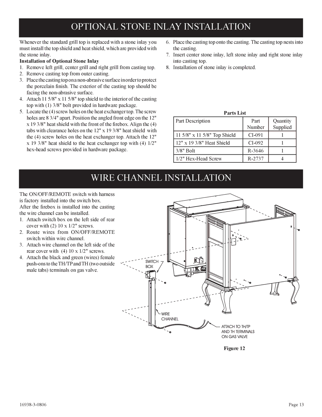
WIRE CHANNEL INSTALLATION
The ON/OFF/REMOTE switch with harness is factory installed into the switch box. After the firebox is installed into the casting the wire channel can be installed.
1.Attach switch box on the left side of rear cover with (2) 10 x 1/2" screws.
2.Route wires from ON/OFF/REMOTE switch within wire channel.
3.Attach wire channel on the left side of the rear cover with (4) 10 x 1/2" screws.
4.Attach the black and green (wires) female
Figure 12
| Page 13 |