WIRING
CIVF-25 ON/OFF/REMOTE Switch
Operation of ON/OFF/REMOTE Switch with no Accessories To ignite main burner, turn the control knob on the gas valve from the PILOT position to the ON position. Turn the ON/OFF/ REMOTE switch from the OFF position to the ON position. The additional green wire and red wire, which are stripped and bare are not used.
Operation of ON/OFF/REMOTE Switch with Accessories 750 Millivolt Wall Thermostat
Connect the green and red, stripped and bare, wires on the ON/ OFF/REMOTE switch wire harness to the wall thermostat. Turn the ON/OFF/REMOTE switch on the wire channel to the REMOTE position. Set the wall thermostat to the desired temperature.
It is important to use wire of a gauge proper for the length of the wire:
RECOMMENDED WIRE GAUGES
Maximum | Wire |
Length | Gauge |
1' to 10' | 18 |
10' to 25' | 16 |
25' to 35' | 14 |
Wall Switch, FWS-1
Connect the green and red, stripped and bare, wires on the ON/OFF/ REMOTE switch wire harness to the wall switch.Turn the ON/OFF/ REMOTE switch on the wire channel to the REMOTE position. Pivot the rocker switch on the
Battery Operated Remote Control,
Note: If batteries fail in
Electric (120 volt) Operated Remote Control,
Note: If electric (120 volt) fails in
Wiring of ON/OFF/REMOTE Switch with 750 Millivolt Wall Thermostat Accessory and Another Accessory
Connect the green and red, stripped and bare, wires on the ON/OFF/ REMOTE switch wire harness to the 750 millivolt wall thermostat AND to the remote receiver that is a component in the
1.Connect (1) wire from the 750 millivolt wall thermostat and (1) wire from appropriate accessory to the GREEN, stripped and bare wire from the ON/OFF/REMOTE wire harness.
2.Connect (1) wire from the 750 millivolt wall thermostat and (1) wire from appropriate accessory to the RED, stripped and bare wire from the ON/OFF/REMOTE wire harness.
Note: When the appliance is in the MANUAL mode and the batteries fail in the
Manual Operation
1.Turn ON/OFF/REMOTE switch on wire channel to REMOTE position.
2.Turn wall thermostat OFF.
3.Turn accessory,
Wall Thermostat Operation
1.Turn the ON/OFF/REMOTE switch on wire channel to REMOTE position.
2.Turn accessory,
3.Turn wall thermostat ON and set appropriate temperature. Wall thermostat will cycle the appliance ON and OFF.
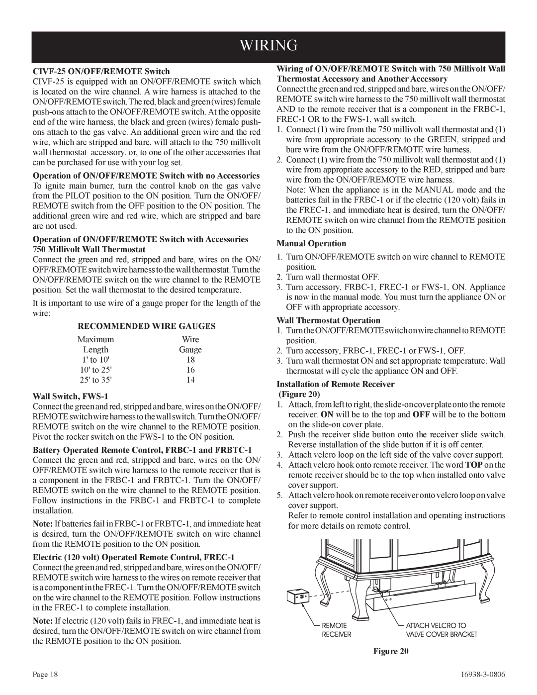
Installation of Remote Receiver (Figure 20)
1.Attach, from left to right, the
2.Push the receiver slide button onto the receiver slide switch. Reverse installation of the slide button if it is off center.
3.Attach velcro loop on the left side of the valve cover support.
4.Attach velcro hook onto remote receiver. The word TOP on the remote receiver should be to the top when installed onto valve cover support.
5.Attach velcro hook on remote receiver onto velcro loop on valve cover support.
Refer to remote control installation and operating instructions for more details on remote control.
Figure 20
Page 18 |
|