Gas Fireplace Heater
The Tahoe Direct Vent Zero Clearance
DIRECT VENT GAS FIREPLACE HEATER MODEL SERIES
MAIN TITLE
IMPORTANT SAFETY INFORMATION
SAFETY INFORMATION FOR USERS OF LP GAS
REQUIREMENTS FOR MASSACHUSETTS
High Altitude
INTRODUCTION
Instructions to Installer
Qualified Installing Agency
FIREPLACE DIMENSIONS
SPECIFICATIONS
LOCATING FIREPLACE
CLEARANCES
GAS SUPPLY
HORIZONTAL VENTING
REAR VENT CONVERSION
VENT SYSTEMS
VERTICAL VENTING
5” Diameter flue 8” Diameter intake vent 1 25 mm
INSTALLATION
Top of Vent 376 mm 125 mm
Combustibles NOT allowed in shaded area
Finishing Figures 12 and
INSTALLATION continued
Flush Mount Mantel Installation Figure
Figure Framing Figure
1.A flat, hard combustible burnable surface
Flush Wall Installation
Figure Combustible Surround Installation
Vent Runs Figures 14, 15, 16, 17 and
HORIZONTAL ONLY, STRAIGHT OUT THE BACK
INSTALLATION continued
CORNER INSTALLATION VERTICAL, 90 ELBOW TO
Figure CORNER INSTALLATION HORIZONTAL, 45 ELBOW
Venting Graph Dimensions in Feet
VENTING FIREPLACE - TOP
Below Grade Installation
VENTING FIREPLACE - TOP continued
TYPICAL BASEMENT INSTALLATION Figure
Cutting the Hole Figures
Positioning the Fireplace
Figure Figure Figure
EXAMPLES - TOP VENT RUN
24” 24” MINIMUM CLEARANCE TO COMBUSTIBLES
VENT CONNECTION
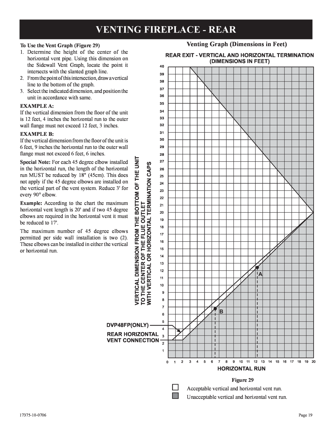
VENTING FIREPLACE - REAR
Venting Graph Dimensions in Feet
DIMENSIONS IN FEET
EXAMPLES - REAR VENT RUN
Vertical Sidewall Installations
TERMINATION CLEARANCES
VENT CLEARANCES
Installing Vent Components Figure
VENT SYSTEM IDENTIFICATION
Installing Support Brackets Figure
FRAMING AND FINISHING
HORIZONTAL TERMINATION
FRAMING AND FINISHING continued
Figure Figure
DVVK-5FFLEX VENT INSTRUCTIONS
Determining Minimum Vent Height Above the Roof
VERTICAL TERMINATION
General Maintenance
Installing the Vent System in a Chase
VERTICAL TERMINATION continued
TOP BRANCH REAR LOG BOTTOM LOG
LOG PLACEMENT 3 LOG SET
Pilot Flame Figure
OPERATING INSTRUCTIONS
750 Millivolt System
Initial Lighting
OPERATING INSTRUCTIONS continued
OPTIONAL THERMOSTAT OPTIONAL WALL SWITCH
STANDING PILOT WIRING DIAGRAM
TO TURN OFF GAS TO FIREPLACE
FOR YOUR SAFETY, READ BEFORE LIGHTING
STANDING PILOT LIGHTING INSTRUCTIONS
LIGHTING INSTRUCTIONS
STANDING PILOT TROUBLESHOOTING
Figure ELECTRICAL CONNECTION Figure
INTERMITTENT PILOT WIRING DIAGRAM
INTERMITTENT PILOT OPERATING INSTRUCTIONS
Installation of Remote Receiver
LIGHTING INSTRUCTIONS
INTERMITTENT PILOT LIGHTING INSTURCTIONS
TO TURN OFF GAS TO APPLIANCE
FOR YOUR SAFETY, READ BEFORE LIGHTING
TRIAL FOR IGNITION Pilot Ignition
INTERMITTENT PILOT TROUBLESHOOTING
CHECKOUT
OPERATION
Main Burner Operation
INTERMITTENT PILOT TROUBLESHOOTING
Safety Lockout
S8600H NORMAL OPERATING SEQUENCE
ACTION
ARC LENGTH
Note If S8600H goes into lockout, reset system
INTERMITTENT PILOT TROUBLESHOOTING continued
S8600H TROUBLESHOOTING GUIDE
Note If S8600H goes into lockout, reset system
LED Troubleshooting
RF STANDING PILOT OPERATING INSTRUCTIONS
Features
Transmitter Signal
RF TRANSMITTER FUNCTIONS
WIRING DIAGRAM WITH BLOWER
RF WIRING DIAGRAM
TO TURN OFF GAS TO APPLIANCE
FOR YOUR SAFETY READ BEFORE LIGHTING
RF STANDING PILOT LIGHTING INSTRUCTIONS
LIGHTING INSTRUCTIONS
MAINTENANCE AND SERVICE
PARTS VIEW
DESCRIPTION
PARTS LIST
INDEX
PART NUMBER
DESCRIPTION
PARTS LIST continued
INDEX
PART NUMBER
FBB4 OPTIONAL VARIABLE SPEED BLOWER INSTALLATION
JUNCTION BOX
FBB4 OPTIONAL VARIABLE SPEED BLOWER INSTALLATION
SWITCH
110 VOLT AC
OPTIONAL BRICK LINER INSTALLATION INSTRUCTIONS
JUNCTION BOX WIRING INSTALLATION INSTRUCTIONS
ACCESSORIES
SERVICE NOTES HOW TO ORDER REPAIR PARTS
Page
SERVICE NOTES
17375-10-0706
17375-10-0706
SERVICE NOTES
Page
Empire Comfort Systems, Inc