RF STANDING PILOT OPERATING INSTRUCTIONS
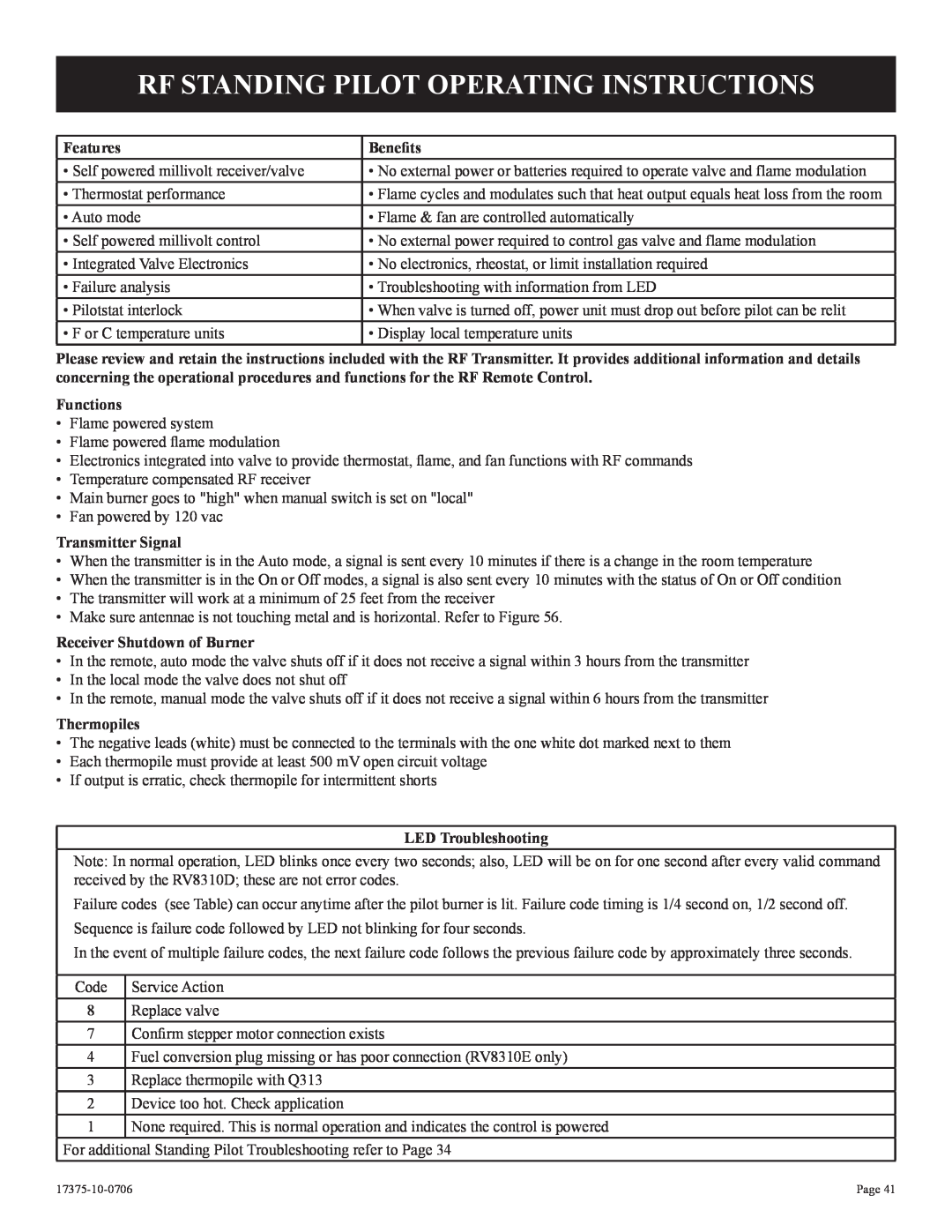
Features | Benefits |
• Self powered millivolt receiver/valve | • No external power or batteries required to operate valve and flame modulation |
• Thermostat performance | • Flame cycles and modulates such that heat output equals heat loss from the room |
• Auto mode | • Flame & fan are controlled automatically |
• Self powered millivolt control | • No external power required to control gas valve and flame modulation |
• Integrated Valve Electronics | • No electronics, rheostat, or limit installation required |
• Failure analysis | • Troubleshooting with information from LED |
• Pilotstat interlock | • When valve is turned off, power unit must drop out before pilot can be relit |
• F or C temperature units | • Display local temperature units |
Please review and retain the instructions included with the RF Transmitter. It provides additional information and details concerning the operational procedures and functions for the RF Remote Control.
Functions
•Flame powered system
•Flame powered flame modulation
•Electronics integrated into valve to provide thermostat, flame, and fan functions with RF commands
•Temperature compensated RF receiver
•Main burner goes to "high" when manual switch is set on "local"
•Fan powered by 120 vac
Transmitter Signal
•When the transmitter is in the Auto mode, a signal is sent every 10 minutes if there is a change in the room temperature
•When the transmitter is in the On or Off modes, a signal is also sent every 10 minutes with the status of On or Off condition
•The transmitter will work at a minimum of 25 feet from the receiver
•Make sure antennae is not touching metal and is horizontal. Refer to Figure 56.
Receiver Shutdown of Burner
•In the remote, auto mode the valve shuts off if it does not receive a signal within 3 hours from the transmitter
•In the local mode the valve does not shut off
•In the remote, manual mode the valve shuts off if it does not receive a signal within 6 hours from the transmitter
Thermopiles
•The negative leads (white) must be connected to the terminals with the one white dot marked next to them
•Each thermopile must provide at least 500 mV open circuit voltage
•If output is erratic, check thermopile for intermittent shorts
LED Troubleshooting
Note: In normal operation, LED blinks once every two seconds; also, LED will be on for one second after every valid command received by the RV8310D; these are not error codes.
Failure codes (see Table) can occur anytime after the pilot burner is lit. Failure code timing is 1/4 second on, 1/2 second off. Sequence is failure code followed by LED not blinking for four seconds.
In the event of multiple failure codes, the next failure code follows the previous failure code by approximately three seconds.
Code Service Action
8Replace valve
7Confirm stepper motor connection exists
4Fuel conversion plug missing or has poor connection (RV8310E only)
3 Replace thermopile with Q313
2 Device too hot. Check application
1 None required. This is normal operation and indicates the control is powered
For additional Standing Pilot Troubleshooting refer to Page 34
Page 41 |