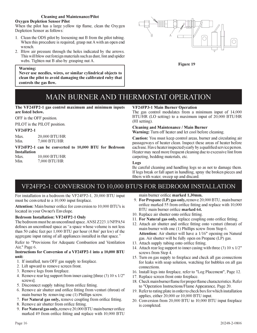
Cleaning and Maintenance/Pilot Oxygen Depletion Sensor Pilot
When the pilot has a large yellow tip flame, clean the Oxygen Depletion Sensor as follows:
1.Clean the ODS pilot by loosening nut B from the pilot tubing. When this procedure is required, grasp nut A with an open end wrench.
2.Blow air pressure through the holes indicated by the arrows. This will blow out foreign materials such as dust, lint and spider webs. Tighten nut B also by grasping nut A.
Warning:
Never use needles, wires, or similar cylindrical objects to clean the pilot to avoid damaging the calibrated ruby that controls the gas flow.
Figure 19
MAIN BURNER AND THERMOSTAT OPERATION
The
OFF is the OFF position.
PILOT is the PILOT position.
VF24FP2-1
Max. | 20,000 BTU/HR |
Min. | 7,000 BTU/HR |
Max.
Min.
VF24FP3-1 Main Burner Operation
The gas control modulates from a minimum input of 14,000 BTU/HR (LO setting) to a maximum input of 20,000 BTU/HR (HI setting).
Cleaning and Maintenance / Main Burner Warning: Turn off heater and let cool before cleaning.
Caution: You must keep control areas, burner and circulating air passageways of heater clean. Inspect these areas of heater before each use. Have heater inspected yearly by a qualified service person. Heater may need more frequent cleaning due to excessive lint from carpeting, bedding materials, etc.
Logs
Be careful cleaning and handling logs so as not to damage them. If logs break or fall apart in handling, spray the broken pieces and fibers with water, sweep up and discard.
For installation in a bedroom the
Attention: Main burner orifice for conversion to 10,000 BTU's is located in your Owner's Envelope.
Bedroom Installation: VF24FP2-1 Only
The bedroom must be an unconfined space. ANSI Z223.1/NFPA54 defines an unconfined space as “a space whose volume is not less than 50 cubic feet per 1,000 BTU per hour (4.8m3 per kw) of the aggregate input rating of all appliances installed in that space.”
Refer to "Provisions for Adequate Combustion and Ventilation Air," Page 6.
Instructions for Conversion of a
1.If installed, turn OFF gas supply to fireplace.
2.Lift upward to remove screen front.
3.Remove logs from fireplace.
4.Remove rear log support from inner casing [three (3) 10 x 1/2" screws].
5.Disconnect supply tubing from orifice fitting.
6.Remove air shutter and orifice fitting from venturi (throat) of main burner by removing one (1) Phillips screw.
7.For Natural gas only, remove coupling from orifice fitting.
8.Remove air shutter from orifice fitting.
9.For Natural gas only, remove 20,000 BTU main burner orifice marked 49 from orifice fitting and replace with 10,000 BTU
main burner orifice marked 1.30mm.
9.For Propane (LP) gas only, remove 20,000 BTU, main burner orifice marked 55 from orifice fitting and replace with 10,000 BTU main burner orifice marked 64.
10. Replace air shutter onto orifice fitting.
11. For Natural gas only, replace coupling onto orifice fitting. 12. Attach air shutter and orifice fitting onto venturi (throat) of
main burner with one (1) Phillips screw from Step 6. Attention: Air shutter will have a 1/16" opening on Natural gas. Air shutter will be fully open on Propane (LP) gas.
13. Attach supply tubing onto orifice fitting.
14. Attach rear log support to inner casing with three (3) 10 x 1/2" screws from Step 4.
15. Turn on gas supply to fireplace and check all gas connections for leaks with soap solution, watching for bubbles on all gas connections.
16. Install logs into fireplace, refer to "Log Placement", Page 12.
17. Replace screen front onto fireplace.
18. Check main burner flame for proper flame characteristics. Refer to "Operation Instructions/Flame Appearance, Page 20.
19. Refer to rating plate in order to check box for which installation applies, either 20,000 or 10,000 BTU input.
20. Conversion from 20,000 BTU to 10,000 BTU input fireplace is completed.
Page 16 |
