|
|
|
|
|
|
|
|
|
| 15 |
|
|
|
|
| 19 |
|
|
|
|
|
|
|
|
|
|
|
|
|
|
|
|
|
|
|
|
|
|
|
|
|
| 20 |
|
| 16 |
|
|
|
|
|
| |
|
|
|
|
|
|
|
|
|
|
|
|
|
|
|
|
|
|
|
|
|
|
|
|
| 21 |
|
| 17 |
|
|
|
|
| ||
|
|
|
|
|
|
|
|
|
|
|
|
|
|
|
|
|
|
| 18 |
|
|
|
|
| 22 |
|
|
|
|
|
|
|
| ||
|
|
|
|
| ||||
| Fig. E |
| 23 |
| ||||
|
|
|
|
|
|
|
| |
|
|
|
|
|
|
|
|
|
15.
16.
17.
18.
19.5/16" Flat Washer (4)
20.7/16" Jam Nut (2)
21.7/16" Locknut (2)
22.
23.
| Fig. F |
|
|
|
| |
|
|
|
|
|
|
|
| 25 |
|
|
|
| 27 |
|
|
|
|
|
|
|
|
|
|
|
|
|
|
|
|
|
| 24 |
|
|
|
|
|
|
|
|
|
| 26 |
|
|
|
| 28 |
|
|
|
|
| ||
24.Table Handle (2)
25.Male Hinge (2)
26.Door Latch
27.Female Hinge (2)
28.Cord Bushing
ASSEMBLY
ASSEMBLY TOOLS REQUIRED
3/8" Wrench | 7/16" Wrench | 4mm Hex Wrench |
5/16" Wrench | 1/2" Wrench | Phillips Screwdriver |
ASSEMBLY TIME ESTIMATE
Approximately
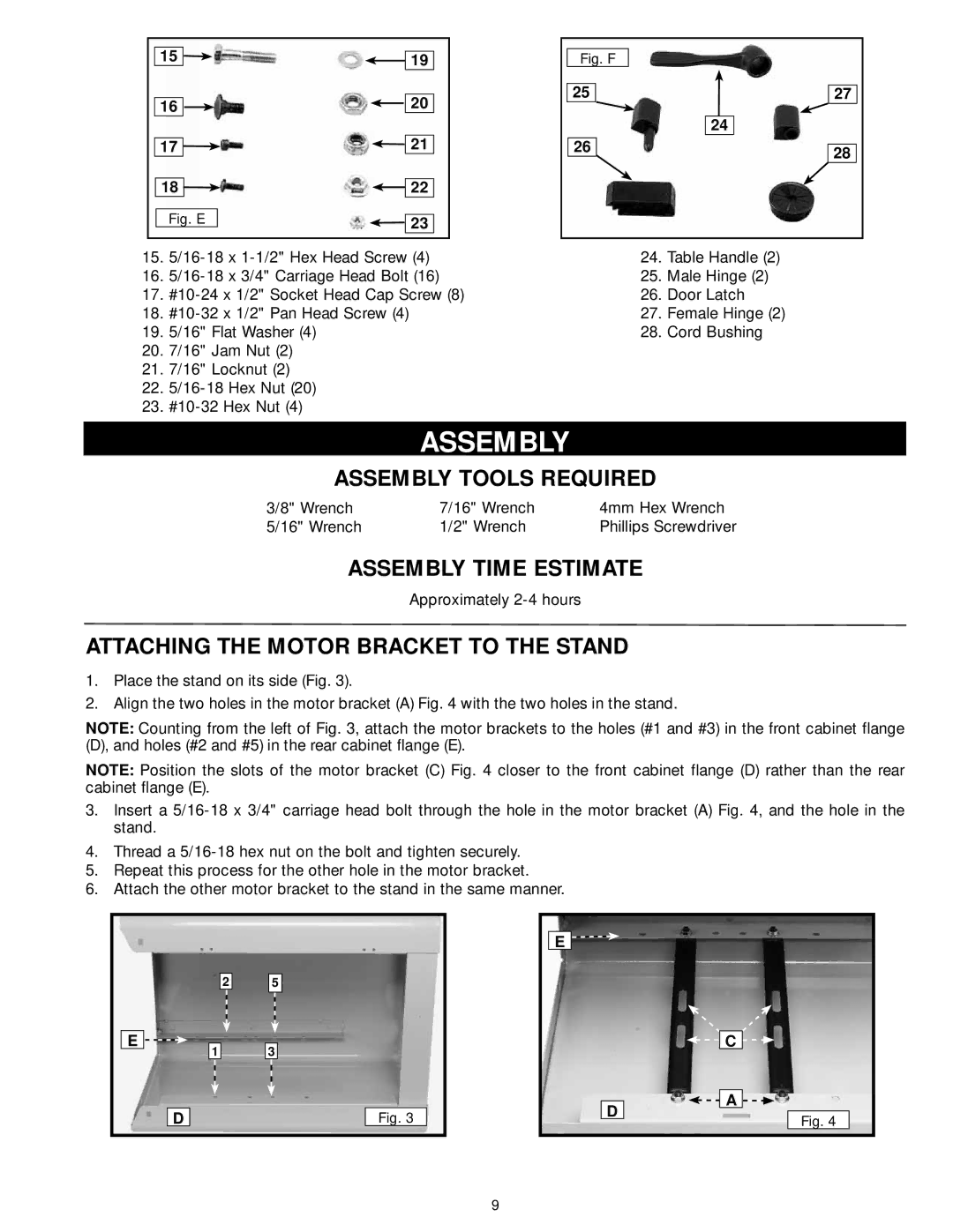
ATTACHING THE MOTOR BRACKET TO THE STAND
1.Place the stand on its side (Fig. 3).
2.Align the two holes in the motor bracket (A) Fig. 4 with the two holes in the stand.
NOTE: Counting from the left of Fig. 3, attach the motor brackets to the holes (#1 and #3) in the front cabinet flange (D), and holes (#2 and #5) in the rear cabinet flange (E).
NOTE: Position the slots of the motor bracket (C) Fig. 4 closer to the front cabinet flange (D) rather than the rear cabinet flange (E).
3.Insert a
4.Thread a
5.Repeat this process for the other hole in the motor bracket.
6.Attach the other motor bracket to the stand in the same manner.
E ![]()
D
2
1
5
3
Fig. 3
E ![]()
![]()
D
C
A
Fig. 4
9