4 Replacement Procedures | 4.15 Display Assembly |
2.Turn the computer face up and open the display panel.
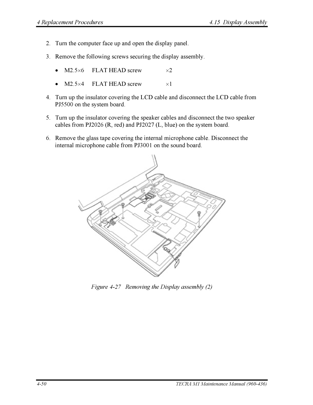
3.Remove the following screws securing the display assembly.
• | M2.5⋅6 | FLAT HEAD screw | ⋅2 |
• | M2.5⋅4 | FLAT HEAD screw | ⋅1 |
4.Turn up the insulator covering the LCD cable and disconnect the LCD cable from PJ5500 on the system board.
5.Turn up the insulator covering the speaker cables and disconnect the two speaker cables from PJ2026 (R, red) and PJ2027 (L, blue) on the system board.
6.Remove the glass tape covering the internal microphone cable. Disconnect the internal microphone cable from PJ3001 on the sound board.
Figure 4-27 Removing the Display assembly (2)
TECRA M1 Maintenance Manual |