4 Replacement Procedures | 4.11 Sensor/Switch Board |
4.11 Sensor/Switch Board
Removing the Sensor/Switch Board
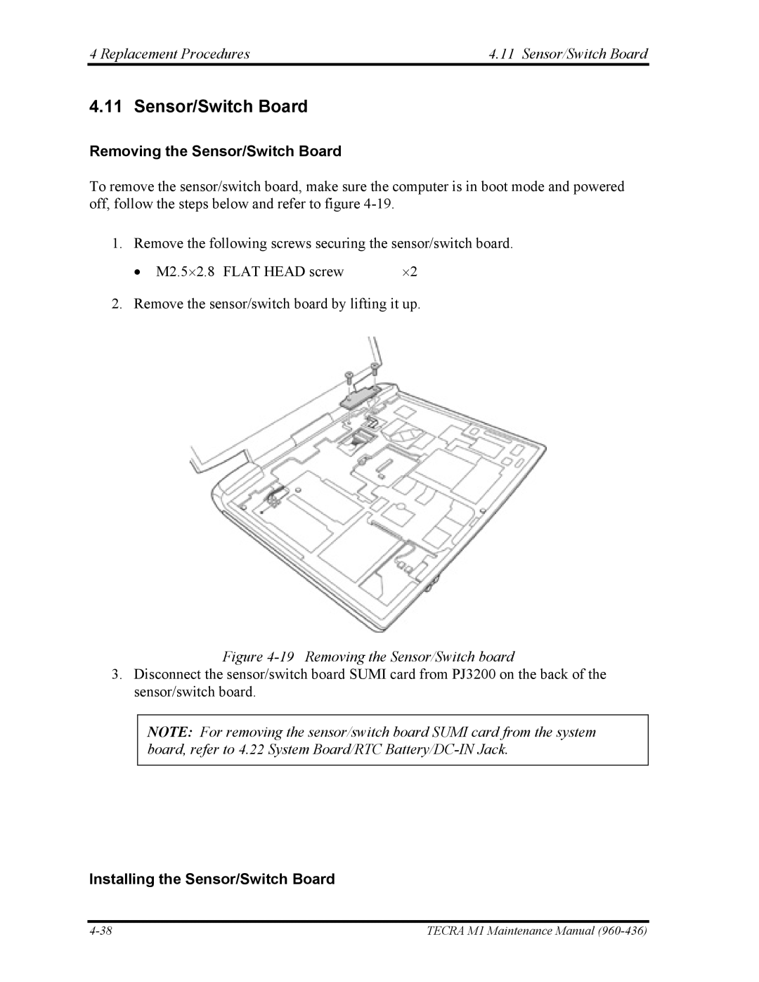
To remove the sensor/switch board, make sure the computer is in boot mode and powered off, follow the steps below and refer to figure
1. Remove the following screws securing the sensor/switch board.
• M2.5⋅2.8 FLAT HEAD screw | ⋅2 |
2. Remove the sensor/switch board by lifting it up.
Figure 4-19 Removing the Sensor/Switch board
3.Disconnect the sensor/switch board SUMI card from PJ3200 on the back of the sensor/switch board.
NOTE: For removing the sensor/switch board SUMI card from the system board, refer to 4.22 System Board/RTC
Installing the Sensor/Switch Board
TECRA M1 Maintenance Manual |
