2.15 Sound Troubleshooting | 2 Troubleshooting Procedures |
Procedure 2 Connector Check
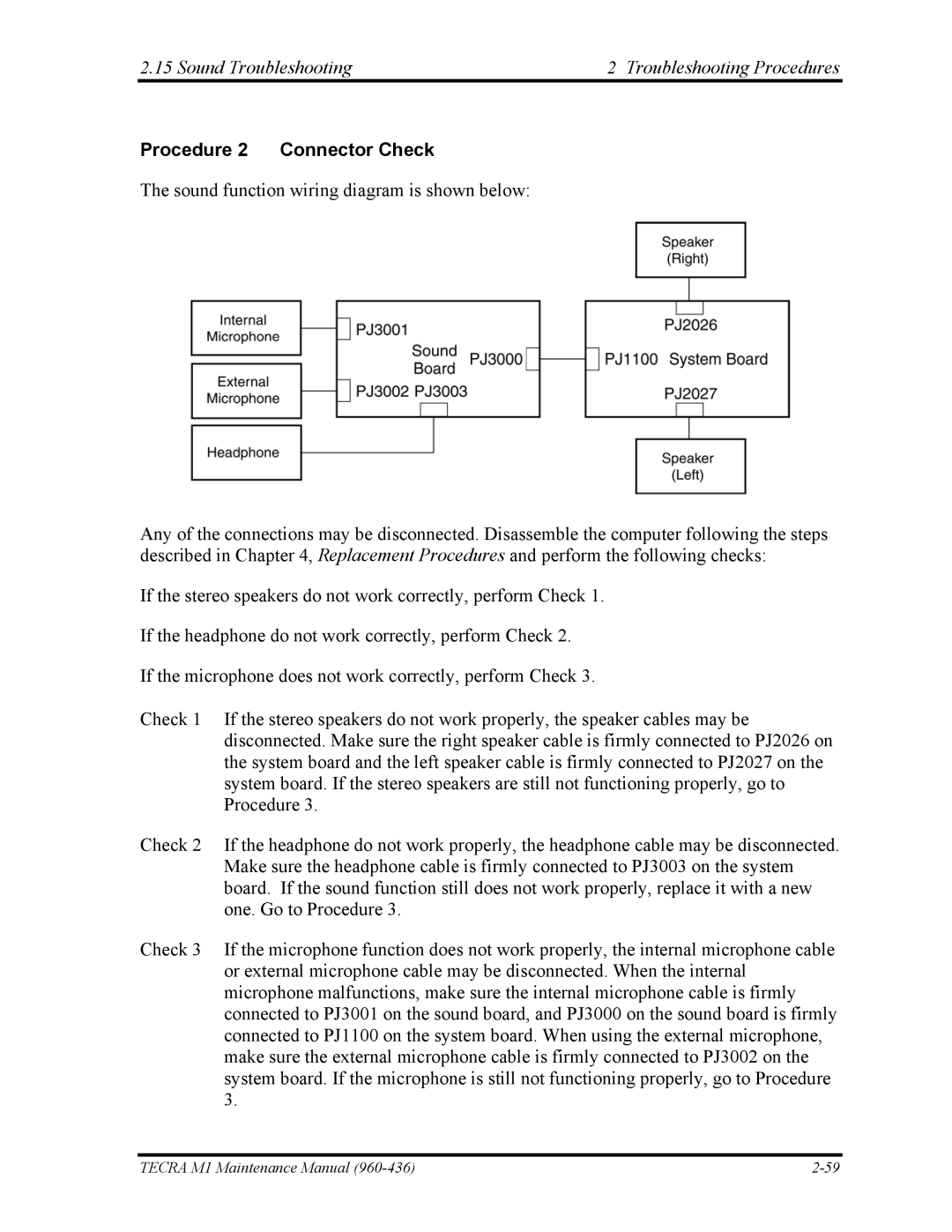
The sound function wiring diagram is shown below:
Any of the connections may be disconnected. Disassemble the computer following the steps described in Chapter 4, Replacement Procedures and perform the following checks:
If the stereo speakers do not work correctly, perform Check 1.
If the headphone do not work correctly, perform Check 2.
If the microphone does not work correctly, perform Check 3.
Check 1 If the stereo speakers do not work properly, the speaker cables may be disconnected. Make sure the right speaker cable is firmly connected to PJ2026 on the system board and the left speaker cable is firmly connected to PJ2027 on the system board. If the stereo speakers are still not functioning properly, go to Procedure 3.
Check 2 If the headphone do not work properly, the headphone cable may be disconnected. Make sure the headphone cable is firmly connected to PJ3003 on the system board. If the sound function still does not work properly, replace it with a new one. Go to Procedure 3.
Check 3 If the microphone function does not work properly, the internal microphone cable
or external microphone cable may be disconnected. When the internal microphone malfunctions, make sure the internal microphone cable is firmly connected to PJ3001 on the sound board, and PJ3000 on the sound board is firmly connected to PJ1100 on the system board. When using the external microphone, make sure the external microphone cable is firmly connected to PJ3002 on the system board. If the microphone is still not functioning properly, go to Procedure 3.
TECRA M1 Maintenance Manual |