4.18 System Board/RTC | 4 Replacement Procedures | ||
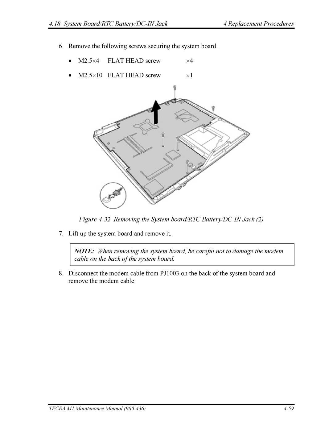
6. Remove the following screws securing the system board. | |||
• | M2.5⋅4 | FLAT HEAD screw | ⋅4 |
• | M2.5⋅10 | FLAT HEAD screw | ⋅1 |
Figure 4-32 Removing the System board/RTC Battery/DC-IN Jack (2) 7. Lift up the system board and remove it.
NOTE: When removing the system board, be careful not to damage the modem cable on the back of the system board.
8.Disconnect the modem cable from PJ1003 on the back of the system board and remove the modem cable.
TECRA M1 Maintenance Manual |