2 Troubleshooting Procedures | 2.5 FDD TroubleshootingSystem Board Troubleshooting |
Table
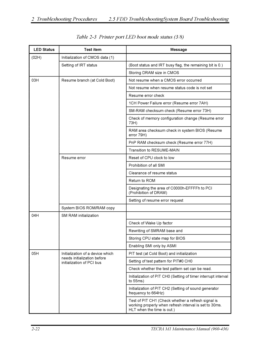
LED Status | Test item | Message |
|
|
|
(02H) | Initialization of CMOS data (1) |
|
|
|
|
| Setting of IRT status | (Boot status and IRT busy flag, the remaining bit is 0.) |
|
|
|
|
| Storing DRAM size in CMOS |
|
|
|
03H | Resume branch (at Cold Boot) | Not resume when a CMOS error occurred |
|
|
|
|
| Not resume when resume status code is not set |
|
|
|
|
| Resume error check |
|
|
|
|
| 1CH Power Failure error (Resume error 7AH) |
|
|
|
|
| |
|
|
|
|
| Check of memory configuration change (Resume error |
|
| 73H) |
|
| RAM area checksum check in system BIOS (Resume |
|
| error 79H) |
|
| PnP RAM checksum check (Resume error 77H) |
|
|
|
|
| Transition to |
|
|
|
| Resume error | Reset of CPU clock to low |
|
|
|
|
| Prohibition of all SMI |
|
|
|
|
| Clearance of resume status |
|
|
|
|
| Return to ROM |
|
|
|
|
| Designating the area of |
|
| (Prohibition of DRAM) |
|
| Setting of resume error request |
|
|
|
| System BIOS ROM/RAM copy |
|
|
|
|
04H | SM RAM initialization |
|
|
|
|
|
| Check of Wake Up factor |
|
|
|
|
| Rewriting of SMRAM base and |
|
|
|
|
| Storing CPU state map for BIOS |
|
|
|
|
| Enabling SMI only by ASMI |
|
|
|
05H | Initialization of a device which | PIT test (at Cold Boot) and initialization |
| needs initialization before |
|
| Setting of test pattern for PIT#0 CH0 | |
| initialization of PCI bus | |
|
| |
|
| Check whether the test pattern set can be read. |
|
|
|
|
| Initialization of PIT CH0 (Setting of timer interrupt interval |
|
| to 55ms) |
|
| Initialization of PIT CH2 (Setting of sound generator |
|
| frequency to 664Hz) |
|
| Test of PIT CH1 (Check whether a refresh signal is |
|
| working properly when refresh interval is set to 30ms. |
|
| HLT when the time is out.) |
|
|
|
TECRA M1 Maintenance Manual |