4 Replacement Procedures | 4.12 Touch Pad |
4.12 Touch Pad
Removing the Touch Pad
To remove the touch pad, follow the steps below and refer to figures
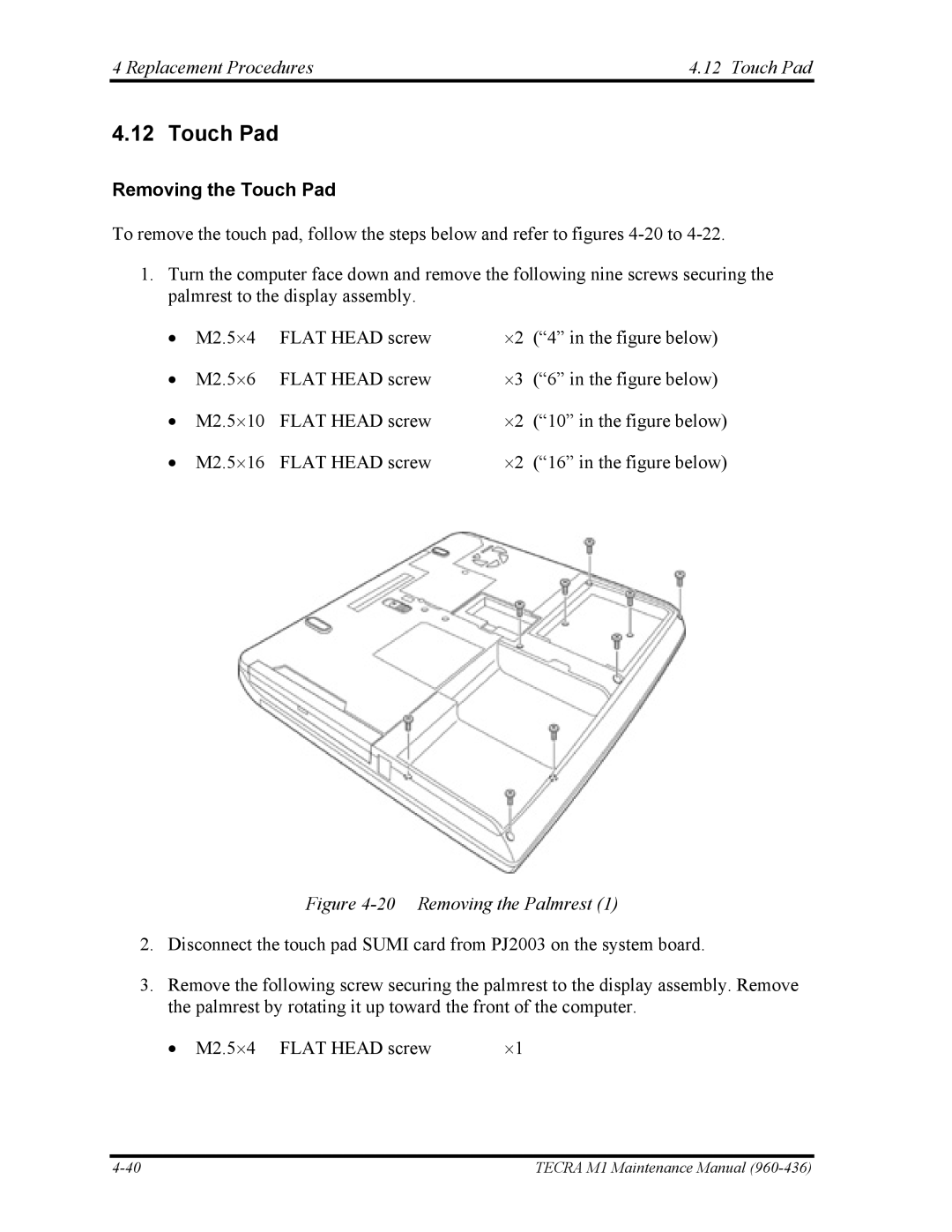
1.Turn the computer face down and remove the following nine screws securing the palmrest to the display assembly.
• | M2.5⋅4 | FLAT HEAD screw | ⋅2 | (“4” in the figure below) |
• | M2.5⋅6 | FLAT HEAD screw | ⋅3 | (“6” in the figure below) |
• | M2.5⋅10 | FLAT HEAD screw | ⋅2 | (“10” in the figure below) |
• | M2.5⋅16 | FLAT HEAD screw | ⋅2 | (“16” in the figure below) |
Figure 4-20 Removing the Palmrest (1)
2.Disconnect the touch pad SUMI card from PJ2003 on the system board.
3.Remove the following screw securing the palmrest to the display assembly. Remove the palmrest by rotating it up toward the front of the computer.
• M2.5⋅4 FLAT HEAD screw | ⋅1 |
TECRA M1 Maintenance Manual |