4 Replacement Procedures | 4.18 System Board/RTC |
Removing the System Board/RTC Battery/DC-IN Jack
To remove the system board/RTC
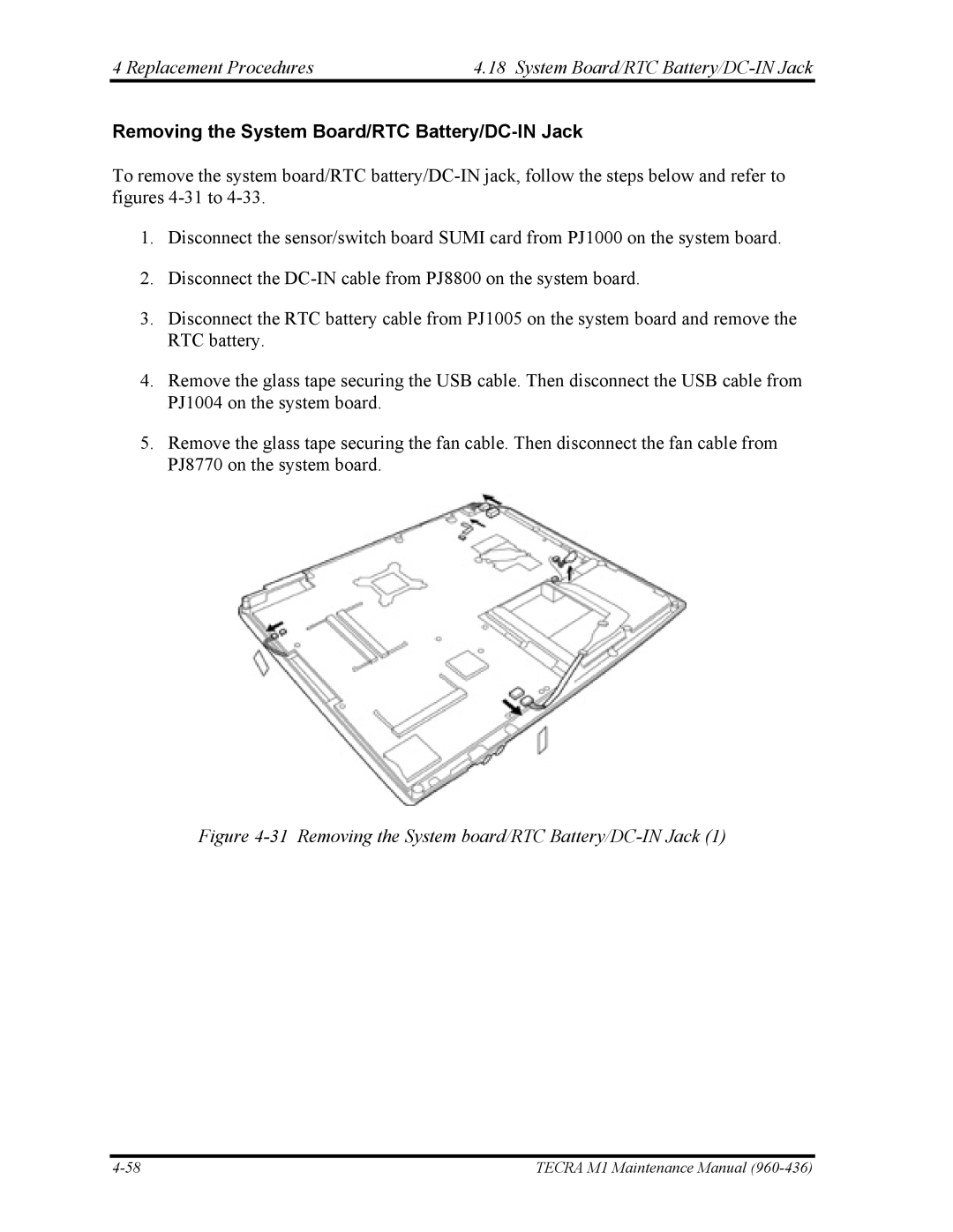
1.Disconnect the sensor/switch board SUMI card from PJ1000 on the system board.
2.Disconnect the
3.Disconnect the RTC battery cable from PJ1005 on the system board and remove the RTC battery.
4.Remove the glass tape securing the USB cable. Then disconnect the USB cable from PJ1004 on the system board.
5.Remove the glass tape securing the fan cable. Then disconnect the fan cable from PJ8770 on the system board.
Figure 4-31 Removing the System board/RTC Battery/DC-IN Jack (1)
TECRA M1 Maintenance Manual |