Connecting to Console Port for Local Management
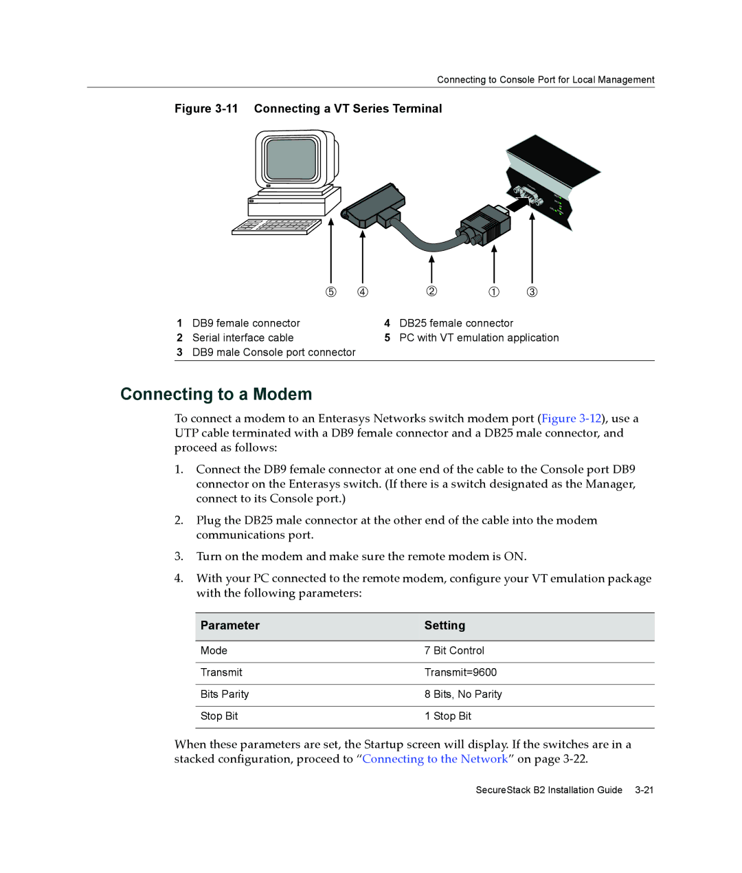
Figure 3-11 Connecting a VT Series Terminal
Console
| M |
| GR |
| RPS |
CPU | UP |
DO | |
| WN |
|
|
|
|
|
|
|
|
|
|
|
|
|
|
|
|
|
|
|
|
|
|
|
|
|
|
|
|
|
|
|
|
|
|
|
|
|
|
|
|
|
|
|
|
|
|
|
|
|
|
|
|
|
|
|
|
|
|
|
|
|
|
|
|
|
|
|
|
|
|
|
|
|
|
|
|
|
|
|
|
|
|
|
|
|
|
|
|
|
|
|
|
|
|
|
|
|
|
|
|
|
|
|
|
|
|
|
|
|
|
|
|
|
|
|
|
|
|
|
| Ä Ã |
| Á | À | Â | |||||||||||
1 | DB9 female connector | 4 | DB25 female connector |
|
| |||||||||||
2 | Serial interface cable | 5 | PC with VT emulation application | |||||||||||||
3DB9 male Console port connector
Connecting to a Modem
To connect a modem to an Enterasys Networks switch modem port (Figure 3‐12), use a UTP cable terminated with a DB9 female connector and a DB25 male connector, and proceed as follows:
1.Connect the DB9 female connector at one end of the cable to the Console port DB9 connector on the Enterasys switch. (If there is a switch designated as the Manager, connect to its Console port.)
2.Plug the DB25 male connector at the other end of the cable into the modem communications port.
3.Turn on the modem and make sure the remote modem is ON.
4.With your PC connected to the remote modem, configure your VT emulation package with the following parameters:
Parameter | Setting | |
|
|
|
Mode | 7 | Bit Control |
|
| |
Transmit | Transmit=9600 | |
|
|
|
Bits Parity | 8 | Bits, No Parity |
|
|
|
Stop Bit | 1 | Stop Bit |
|
|
|
When these parameters are set, the Startup screen will display. If the switches are in a stacked configuration, proceed to “Connecting to the Network” on page 3‐22.
SecureStack B2 Installation Guide