Installation
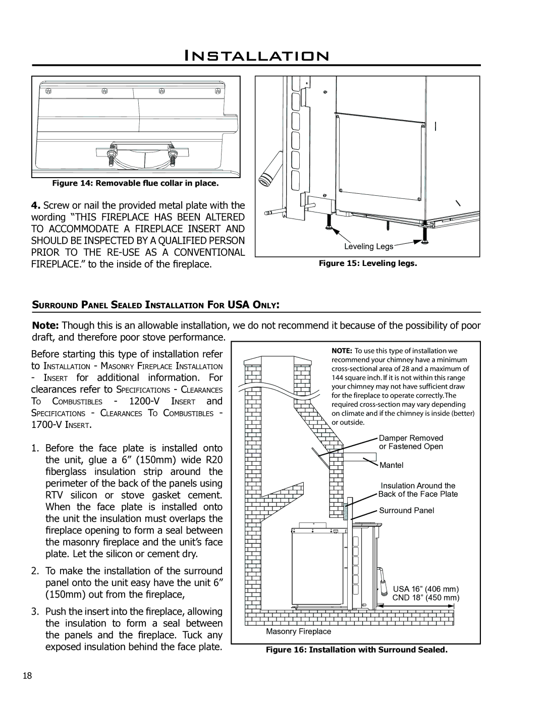
Figure 14: Removable flue collar in place.
4.Screw or nail the provided metal plate with the wording “THIS FIREPLACE HAS BEEN ALTERED TO ACCOMMODATE A FIREPLACE INSERT AND SHOULD BE INSPECTED BY A QUALIFIED PERSON PRIOR TO THE
Leveling Legs ![]()
Figure 15: Leveling legs.
SURROUND PANEL SEALED INSTALLATION FOR USA ONLY:
Note: Though this is an allowable installation, we do not recommend it because of the possibility of poor draft, and therefore poor stove performance.
Before starting this type of installation refer
to INSTALLATION - MASONRY FIREPLACE INSTALLATION
-INSERT for additional information. For
clearances refer to SPECIFICATIONS - CLEARANCES TO COMBUSTIBLES -
SPECIFICATIONS - CLEARANCES TO COMBUSTIBLES -
1.Before the face plate is installed onto the unit, glue a 6” (150mm) wide R20 fiberglass insulation strip around the perimeter of the back of the panels using RTV silicon or stove gasket cement. When the face plate is installed onto the unit the insulation must overlaps the fireplace opening to form a seal between the masonry fireplace and the unit’s face plate. Let the silicon or cement dry.
2.To make the installation of the surround panel onto the unit easy have the unit 6” (150mm) out from the fireplace,
3.Push the insert into the fireplace, allowing the insulation to form a seal between the panels and the fireplace. Tuck any exposed insulation behind the face plate.
����� �� ��� ���� ���� �� ������������ �� |
��������� ���� ������� ���� � ������� |
��������������� ���� �� �� ��� � ������� �� |
��� ������ ����� �� �� �� ��� ������ ���� ����� |
���� ������� ��� ��� ���� ���������� ���� |
��� ��� ��������� �� ������� ������������� |
�������� ������������� ��� ���� ��������� |
�� ������� ��� �� ��� ������� �� ������ �������� |
�� �������� |
Damper Removed |
or Fastened Open |
Mantel |
Insulation Around the |
Back of the Face Plate |
Surround Panel |
USA 16” (406 mm) |
CND 18” (450 mm) |
Masonry Fireplace
Figure 16: Installation with Surround Sealed.
18
