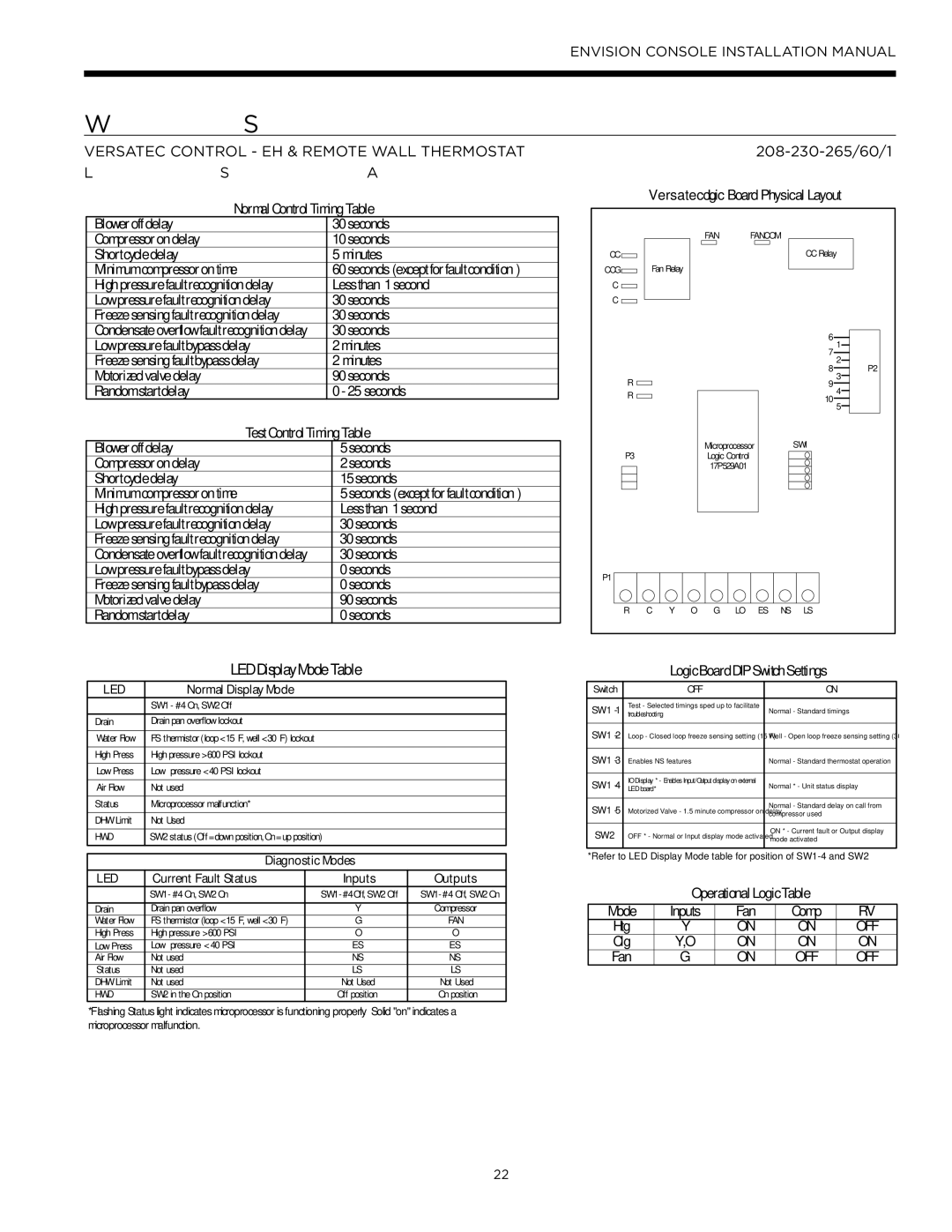
IM1609 10, IM1609 08 specifications
Envision Peripherals has carved a niche in the realm of advanced display technology, and its IM1609 10 and IM1609 08 models are no exception. These cutting-edge monitors are designed to meet a wide array of professional needs while delivering outstanding performance and visual clarity.One of the standout features of the IM1609 10 is its impressive 16:9 aspect ratio and full HD resolution. This setup ensures that users receive crisp and vibrant visuals, whether they're working on intricate designs, analyzing data, or enjoying multimedia content. The IM1609 08 shares similar visual capabilities, making both models ideal for professionals in graphic design, video editing, and other visually intensive fields.
Both displays incorporate advanced LED backlight technology, which not only enhances color accuracy but also contributes to energy efficiency. Users can expect deeper blacks and brighter whites, resulting in a more dynamic visual experience. Furthermore, the IM1609 series features wide viewing angles, allowing multiple users to view the screen simultaneously without loss of quality or color distortion.
In terms of connectivity, the IM1609 10 and IM1609 08 come equipped with a range of ports, including HDMI, DisplayPort, and USB-C. This versatility ensures seamless integration with various devices, from laptops and desktops to media players and more. The USB-C port also allows for quick data transfer and charging options, catering to the needs of modern tech users.
Ergonomics is another key characteristic of the IM1609 series. With adjustable stands that allow for height, tilt, and swivel adjustments, users can customize their viewing experience for maximum comfort, reducing neck and eye strain during long working hours.
Additionally, the IM1609 monitors feature built-in blue light filters and flicker-free technology, which help to create a healthier viewing environment by minimizing eye fatigue. This consideration for user well-being is increasingly important in today’s tech-driven world, especially for professionals who spend significant time in front of screens.
Overall, Envision Peripherals’ IM1609 10 and IM1609 08 models represent the company’s commitment to blending performance, usability, and comfort into one seamless package. Whether for professional or personal use, these monitors deliver exceptional quality, making them a noteworthy addition to any workspace.

