ASSEMBLING ACCESSORY 50-314
STAND
If you purchased the accessory
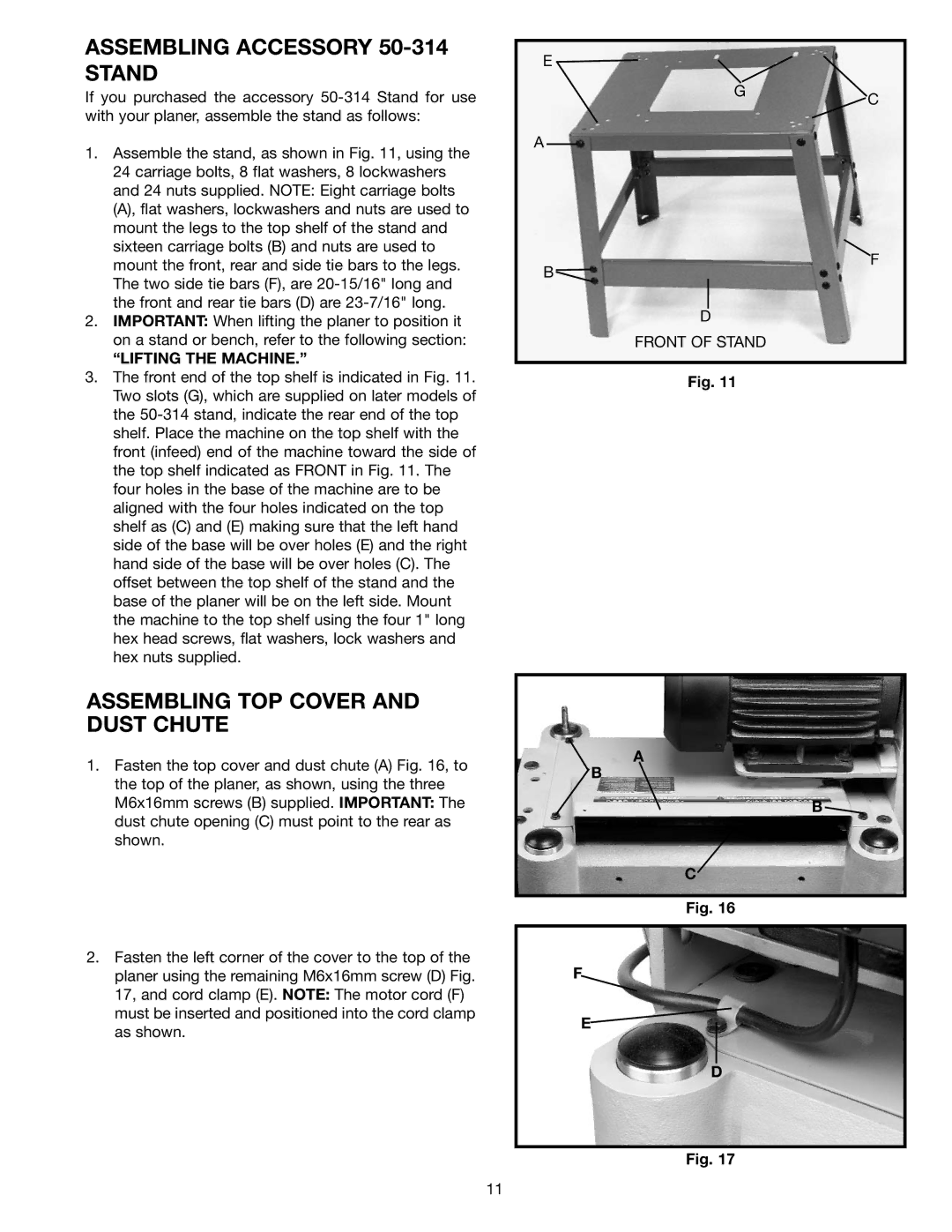
1.Assemble the stand, as shown in Fig. 11, using the 24 carriage bolts, 8 flat washers, 8 lockwashers and 24 nuts supplied. NOTE: Eight carriage bolts (A), flat washers, lockwashers and nuts are used to mount the legs to the top shelf of the stand and sixteen carriage bolts (B) and nuts are used to mount the front, rear and side tie bars to the legs. The two side tie bars (F), are
2.IMPORTANT: When lifting the planer to position it on a stand or bench, refer to the following section:
“LIFTING THE MACHINE.”
3.The front end of the top shelf is indicated in Fig. 11. Two slots (G), which are supplied on later models of the
ASSEMBLING TOP COVER AND DUST CHUTE
1.Fasten the top cover and dust chute (A) Fig. 16, to the top of the planer, as shown, using the three M6x16mm screws (B) supplied. IMPORTANT: The dust chute opening (C) must point to the rear as shown.
2.Fasten the left corner of the cover to the top of the planer using the remaining M6x16mm screw (D) Fig. 17, and cord clamp (E). NOTE: The motor cord (F) must be inserted and positioned into the cord clamp as shown.
E ![]()
GC
A
F
B ![]()
D
FRONT OF STAND
Fig. 11
A
B
B ![]()
C
Fig. 16
F
E
D
Fig. 17
11