THREE PHASE OPERATION
Three phase MACHINES are not supplied with a power cord. They must be permanently connected to the building electrical system and grounded according to the National Electrical Code. Since they must be permanently connected to the building electrical system, extension cords cannot be used with three phase MACHINES.
200-220 VOLT, THREE PHASE OPERATION
If the motor on your machine is wired for
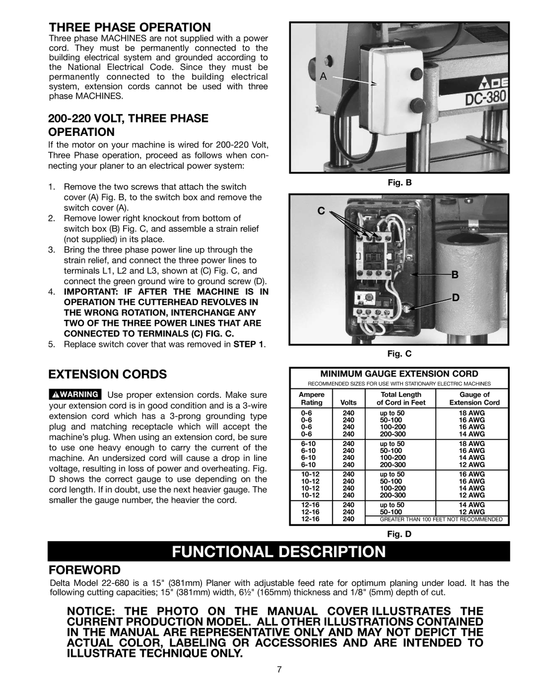
1.Remove the two screws that attach the switch cover (A) Fig. B, to the switch box and remove the switch cover (A).
2.Remove lower right knockout from bottom of switch box (B) Fig. C, and assemble a strain relief (not supplied) in its place.
3.Bring the three phase power line up through the strain relief, and connect the three power lines to terminals L1, L2 and L3, shown at (C) Fig. C, and connect the green ground wire to ground screw (D).
4.IMPORTANT: IF AFTER THE MACHINE IS IN OPERATION THE CUTTERHEAD REVOLVES IN THE WRONG ROTATION, INTERCHANGE ANY TWO OF THE THREE POWER LINES THAT ARE CONNECTED TO TERMINALS (C) FIG. C.
5.Replace switch cover that was removed in STEP 1.
EXTENSION CORDS
![]() Use proper extension cords. Make sure your extension cord is in good condition and is a
Use proper extension cords. Make sure your extension cord is in good condition and is a
A ![]()
Fig. B
C
B
D
Fig. C
MINIMUM GAUGE EXTENSION CORD
RECOMMENDED SIZES FOR USE WITH STATIONARY ELECTRIC MACHINES
Ampere |
| Total Length | Gauge of |
Rating | Volts | of Cord in Feet | Extension Cord |
|
|
|
|
240 | up to 50 | 18 AWG | |
240 | 16 AWG | ||
240 | 16 AWG | ||
240 | 14 AWG | ||
240 | up to 50 | 18 AWG | |
240 | 16 AWG | ||
240 | 14 AWG | ||
240 | 12 AWG | ||
240 | up to 50 | 16 AWG | |
240 | 16 AWG | ||
240 | 14 AWG | ||
240 | 12 AWG | ||
240 | up to 50 | 14 AWG | |
240 | 12 AWG | ||
240 | GREATER THAN 100 | FEET NOT RECOMMENDED | |
|
|
|
|
Fig. D
FUNCTIONAL DESCRIPTION
FOREWORD
Delta Model
NOTICE: THE PHOTO ON THE MANUAL COVER ILLUSTRATES THE CURRENT PRODUCTION MODEL. ALL OTHER ILLUSTRATIONS CONTAINED IN THE MANUAL ARE REPRESENTATIVE ONLY AND MAY NOT DEPICT THE ACTUAL COLOR, LABELING OR ACCESSORIES AND ARE INTENDED TO ILLUSTRATE TECHNIQUE ONLY.
7