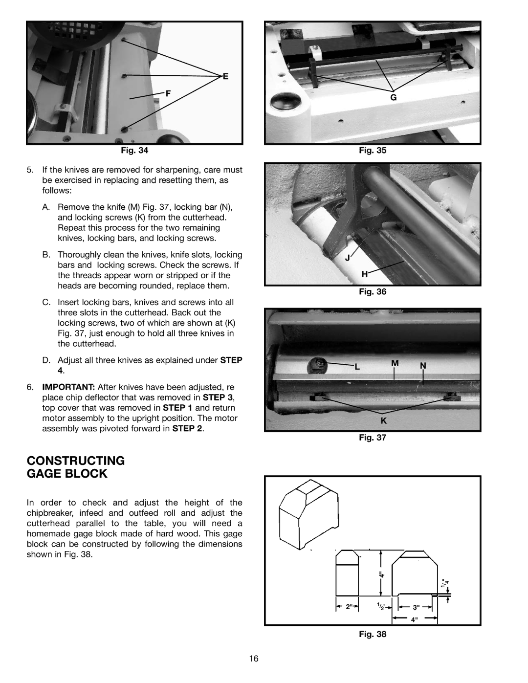
E
![]() F
F
Fig. 34
5.If the knives are removed for sharpening, care must be exercised in replacing and resetting them, as follows:
A.Remove the knife (M) Fig. 37, locking bar (N), and locking screws (K) from the cutterhead. Repeat this process for the two remaining knives, locking bars, and locking screws.
B.Thoroughly clean the knives, knife slots, locking bars and locking screws. Check the screws. If the threads appear worn or stripped or if the heads are becoming rounded, replace them.
C.Insert locking bars, knives and screws into all three slots in the cutterhead. Back out the locking screws, two of which are shown at (K) Fig. 37, just enough to hold all three knives in the cutterhead.
D.Adjust all three knives as explained under STEP 4.
6.IMPORTANT: After knives have been adjusted, re place chip deflector that was removed in STEP 3, top cover that was removed in STEP 1 and return motor assembly to the upright position. The motor assembly was pivoted forward in STEP 2.
CONSTRUCTING
GAGE BLOCK
In order to check and adjust the height of the chipbreaker, infeed and outfeed roll and adjust the cutterhead parallel to the table, you will need a homemade gage block made of hard wood. This gage block can be constructed by following the dimensions shown in Fig. 38.
G
Fig. 35
J
H
Fig. 36
![]() L M N
L M N
K
Fig. 37
4"
1/ " 4
2" 1/2" 3"
4"
Fig. 38
16