ADJUSTING SPRING TENSION OF INFEED AND OUTFEED ROLLERS
The infeed and outfeed rollers are those parts of your planer that feed the stock while it is being planed. The feed rollers are under spring tension and this tension must be sufficient to feed the stock uniformly through the planer without slipping but should not be too tight that it causes damage to the board. The tension should also be equal at both ends of each roller.
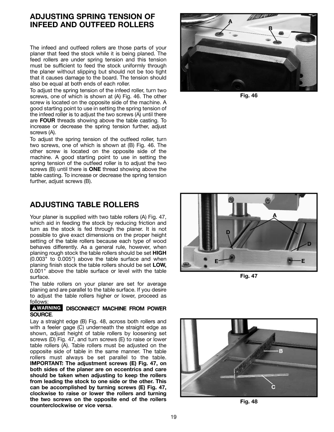
To adjust the spring tension of the infeed roller, turn two screws, one of which is shown at (A) Fig. 46. The other screw is located on the opposite side of the machine. A good starting point to use in setting the spring tension of the infeed roller is to adjust the two screws (A) until there are FOUR threads showing above the table casting. To increase or decrease the spring tension further, adjust screws (A).
To adjust the spring tension of the outfeed roller, turn two screws, one of which is shown at (B) Fig. 46. The other screw is located on the opposite side of the machine. A good starting point to use in setting the spring tension of the outfeed roller is to adjust the two screws (B) until there is ONE thread showing above the table casting. To increase or decrease the spring tension further, adjust screws (B).
ADJUSTING TABLE ROLLERS
Your planer is supplied with two table rollers (A) Fig. 47, which aid in feeding the stock by reducing friction and turn as the stock is fed through the planer. It is not possible to give exact dimensions on the proper height setting of the table rollers because each type of wood behaves differently. As a general rule, however, when planing rough stock the table rollers should be set HIGH (0.003" to 0.005") above the table surface and when planing finish stock the table rollers should be set LOW, 0.001" above the table surface or level with the table surface.
The table rollers on your planer are set for average planing and are parallel to the table surface. If you desire to adjust the table rollers higher or lower, proceed as follows:
 DISCONNECT MACHINE FROM POWER SOURCE.
Lay a straight edge (B) Fig. 48, across both rollers and with a feeler gage (C) underneath the straight edge as shown, adjust height of table rollers by loosening set screws (D) Fig. 47, and turn screws (E) to raise or lower table rollers (A). Table rollers must be adjusted on the opposite side of table in the same manner. The table rollers must always be set parallel to the table.
IMPORTANT: The adjustment screws (E) Fig. 47, on both sides of the planer are on eccentrics and care should be taken when adjusting to keep the rollers from leading the stock to one side or the other. This can be accomplished by turning screws (E) Fig. 47, clockwise to raise or lower the rollers and turning the two screws on the opposite end of the rollers counterclockwise or vice versa.
A
B
Fig. 46
A
D
![]() D
D
E![]()
![]() E
E
Fig. 47
B
C
Fig. 48
19
