ASSEMBLY
![]() FOR YOUR OWN SAFETY, DO NOT CONNECT THE MACHINE TO THE POWER SOURCE UNTIL THE MACHINE IS COMPLETELY ASSEMBLED AND YOU READ AND UNDERSTAND THE ENTIRE INSTRUCTION MANUAL.
FOR YOUR OWN SAFETY, DO NOT CONNECT THE MACHINE TO THE POWER SOURCE UNTIL THE MACHINE IS COMPLETELY ASSEMBLED AND YOU READ AND UNDERSTAND THE ENTIRE INSTRUCTION MANUAL.
ASSEMBLY TOOLS REQUIRED
1) | - Open end wrench (10 and 12mm) - provided | 5) - Hex wrench (3mm) - provided |
2) | - Open end wrench (14 and 17mm) - provided | 6) - Hex wrench (2.5mm) - provided |
3) | - Hex wrench (6mm) - provided | 7) - 10, 12, 14, 17mm Sockets - not provided |
4) | - Hex wrench (5mm) - provided | 8) - 2 - 2 x 4’s - not provided |
ASSEMBLY TIME ESTIMATE - 2~3 hrs.
CUTTINGHEAD RAISING AND LOWERING HANDWHEEL
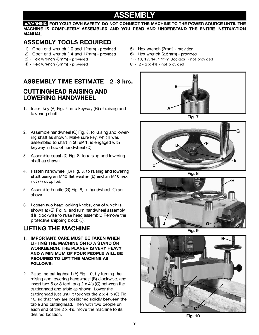
1.Insert key (A) Fig. 7, into keyway (B) of raising and lowering shaft.
2.Assemble handwheel (C) Fig. 8, to raising and lower- ing shaft as shown. Make sure key, which was assembled to shaft in STEP 1, is engaged with keyway in hub of handwheel (C).
3.Assemble decal (D) Fig. 8, to raising and lowering shaft as shown.
4.Fasten handwheel (C) Fig. 8, to raising and lowering shaft using an M10 flat washer (E) and an M10 hex nut (F) supplied.
5.Assemble handle (G) Fig. 8, to handwheel (C) as shown.
6.Loosen two head locking knobs, one of which is shown at (G) Fig. 9, and turn handwheel assembly
(H)clockwise to raise head assembly. Remove the protective shipping block (J).
LIFTING THE MACHINE
1.IMPORTANT: CARE MUST BE TAKEN WHEN LIFTING THE MACHINE ONTO A STAND OR WORKBENCH. THE PLANER IS VERY HEAVY AND A MINIMUM OF FOUR PEOPLE WILL BE REQUIRED TO LIFT THE MACHINE AS FOLLOWS:
2.Raise the cuttinghead (A) Fig. 10, by turning the raising and lowering handwheel (B) clockwise, and insert two 6 or 8 foot long 2 x 4’s (C) between the cuttinghead and table as shown. Lower the cuttinghead just until it touches the 2 x 4 ‘s (C) Fig. 10, so that they are positioned solidly between the table and cuttinghead. Then with two people on each end of the 2 x 4’s, move the machine to its desired location.
B
A
Fig. 7
G
D![]() F
F
![]() E
E
C
Fig. 8
![]() H
H
JG
Fig. 9
B![]()
AC![]()
Fig. 10
9