CHECKING, ADJUSTING AND REPLACING KNIVES
To check, adjust or replace the knives, proceed as follows:
 DISCONNECT MACHINE FROM POWER SOURCE.
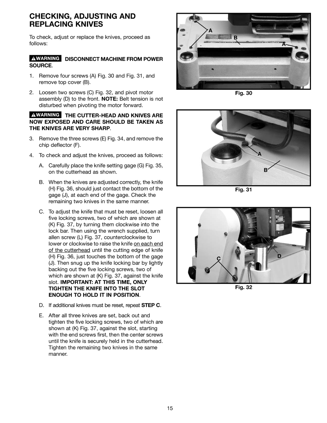
1.Remove four screws (A) Fig. 30 and Fig. 31, and remove top cover (B).
2.Loosen two screws (C) Fig. 32, and pivot motor assembly (D) to the front. NOTE: Belt tension is not disturbed when pivoting the motor forward.
![]() THE
THE
3.Remove the three screws (E) Fig. 34, and remove the chip deflector (F).
4.To check and adjust the knives, proceed as follows:
A.Carefully place the knife setting gage (G) Fig. 35, on the cutterhead as shown.
B.When the knives are adjusted correctly, the knife
(H)Fig. 36, should just contact the bottom of the gage (J), at each end of the gage. Check the remaining two knives in the same manner.
C.To adjust the knife that must be reset, loosen all five locking screws, two of which are shown at
(K)Fig. 37, by turning them clockwise into the lock bar. Then using the wrench supplied, turn allen screw (L) Fig. 37, counterclockwise to lower or clockwise to raise the knife on each end of the cutterhead until the cutting edge of knife
(H)Fig. 36, just touches the bottom of the gage
(J).Then snug up the knife locking bar by lightly backing out the five locking screws, two of which are shown at (K) Fig. 37, against the knife slot. IMPORTANT: AT THIS TIME, ONLY
TIGHTEN THE KNIFE INTO THE SLOT ENOUGH TO HOLD IT IN POSITION.
D.If additional knives must be reset, repeat STEP C.
E.After all three knives are set, back out and tighten the five locking screws, two of which are shown at (K) Fig. 37, against the slot, starting with the end screws first, then the center screws until the knife is securely held in the cutterhead. Tighten the remaining two knives in the same manner.
A
B
A![]()
Fig. 30
A
B
Fig. 31
CD
Fig. 32
15