Connecting the Cash Drawer
Use the cash drawer handled by EPSON or your dealer.
Connecting the Drawer Kick-out Cable
•Specifications of drawers differ depending on makers or models. When you use a
drawer other than specified, make sure its specification meets the following con- WARNING ditions.
Otherwise, devices may be damaged.
∗The load, such as a drawer
∗When the drawer open/close signal is used, a switch must be provided between drawer
∗The resistance of the load, such as a drawer
∗Be sure to use the 24V power output on
•Use a shield cable for the drawer connector cable.
•Two driver transistors cannot be energized simultaneously.
•Leave intervals longer than 4 times the drawer driving pulse when sending it continuously.
•Be sure to use the printer power supply (connector pin 4) for the drawer power source.
•Do not insert a telephone line into the drawer
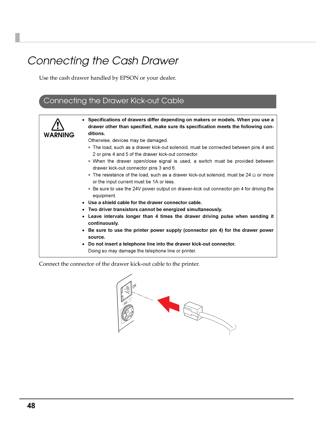
Connect the connector of the drawer
DK
24V
48