LBI-39055
PA Board(s). See Table 9 for details. All relay connections are isolated from ground.
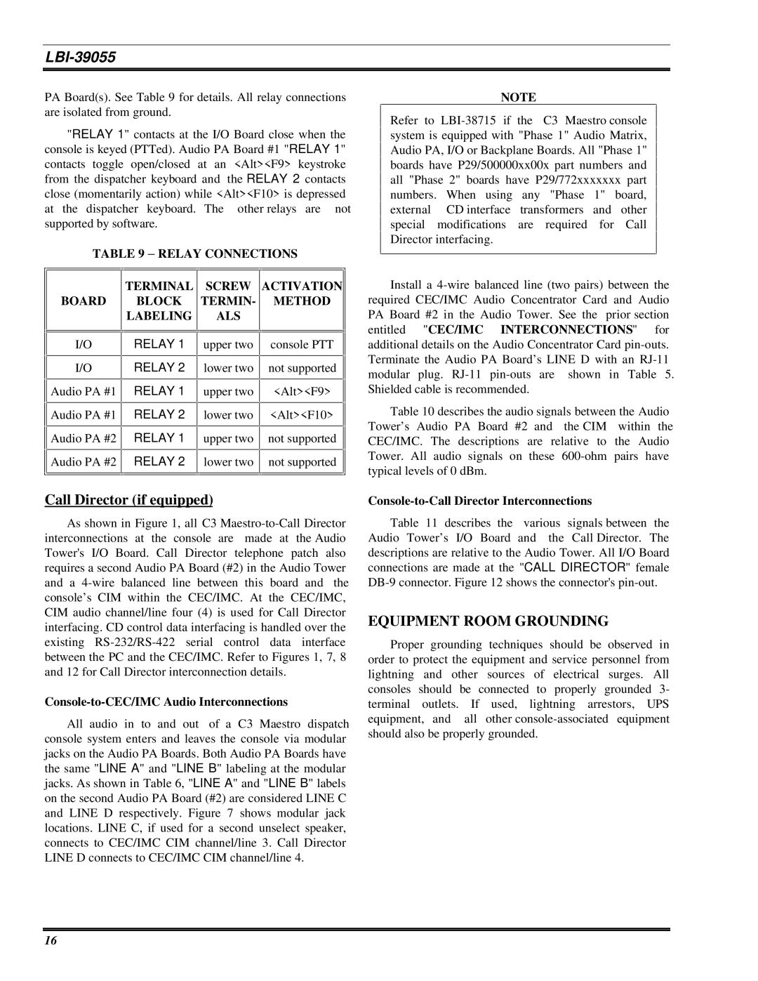
"RELAY 1" contacts at the I/O Board close when the console is keyed (PTTed). Audio PA Board #1 "RELAY 1" contacts toggle open/closed at an <Alt><F9> keystroke from the dispatcher keyboard and the RELAY 2 contacts close (momentarily action) while <Alt><F10> is depressed at the dispatcher keyboard. The other relays are not supported by software.
TABLE 9 − RELAY CONNECTIONS
|
|
|
|
|
|
|
|
|
|
|
| TERMINAL |
| SCREW | ACTIVATION |
| |
| BOARD |
| BLOCK |
| TERMIN- |
| METHOD |
|
|
|
| LABELING |
| ALS |
|
|
|
|
|
|
|
|
|
|
|
|
|
|
|
|
|
|
|
|
|
NOTE
Refer to
Install a
I/O
I/O
![]()
![]() Audio PA #1
Audio PA #1
![]()
![]() Audio PA #1
Audio PA #1
![]()
![]() Audio PA #2
Audio PA #2
![]()
![]() Audio PA #2
Audio PA #2
RELAY 1
RELAY 2
RELAY 1
RELAY 2
RELAY 1
RELAY 2
upper two
lower two
upper two
lower two
upper two
lower two
console PTT
not supported
<Alt><F9>
<Alt><F10>
not supported
not supported
additional details on the Audio Concentrator Card
Table 10 describes the audio signals between the Audio Tower’s Audio PA Board #2 and the CIM within the CEC/IMC. The descriptions are relative to the Audio Tower. All audio signals on these
Call Director (if equipped)
As shown in Figure 1, all C3
Console-to-CEC/IMC Audio Interconnections
All audio in to and out of a C3 Maestro dispatch console system enters and leaves the console via modular jacks on the Audio PA Boards. Both Audio PA Boards have the same "LINE A" and "LINE B" labeling at the modular jacks. As shown in Table 6, "LINE A" and "LINE B" labels on the second Audio PA Board (#2) are considered LINE C and LINE D respectively. Figure 7 shows modular jack locations. LINE C, if used for a second unselect speaker, connects to CEC/IMC CIM channel/line 3. Call Director LINE D connects to CEC/IMC CIM channel/line 4.
Console-to-Call Director Interconnections
Table 11 describes the various signals between the Audio Tower’s I/O Board and the Call Director. The descriptions are relative to the Audio Tower. All I/O Board connections are made at the "CALL DIRECTOR" female
EQUIPMENT ROOM GROUNDING
Proper grounding techniques should be observed in order to protect the equipment and service personnel from lightning and other sources of electrical surges. All consoles should be connected to properly grounded 3- terminal outlets. If used, lightning arrestors, UPS equipment, and all other
16