LBI-39055
Firmware
EPROM integrated circuit U4 on the Logic Board stores the operating program firmware for the
Installation Into The PC
The Logic Board is installed in an expansion slot inside the PC. Although it can be installed in any slot, installing it in the slot furthest from the PC's internal power supply is recommended. If field installation is necessary, follow this procedure:
1. | Review the | procedures in | the documentation |
| included with the PC related to expansion board | ||
| installation. |
|
|
2. | If necessary, | ||
| disconnect it from the ac power source. | ||
3. | Remove the | outside cover | from the PC in |
| accordance with the manufacturer's instructions. | ||
Audio PA Board(s)
SW1 − Maximum Speaker Power Level DIP Switch
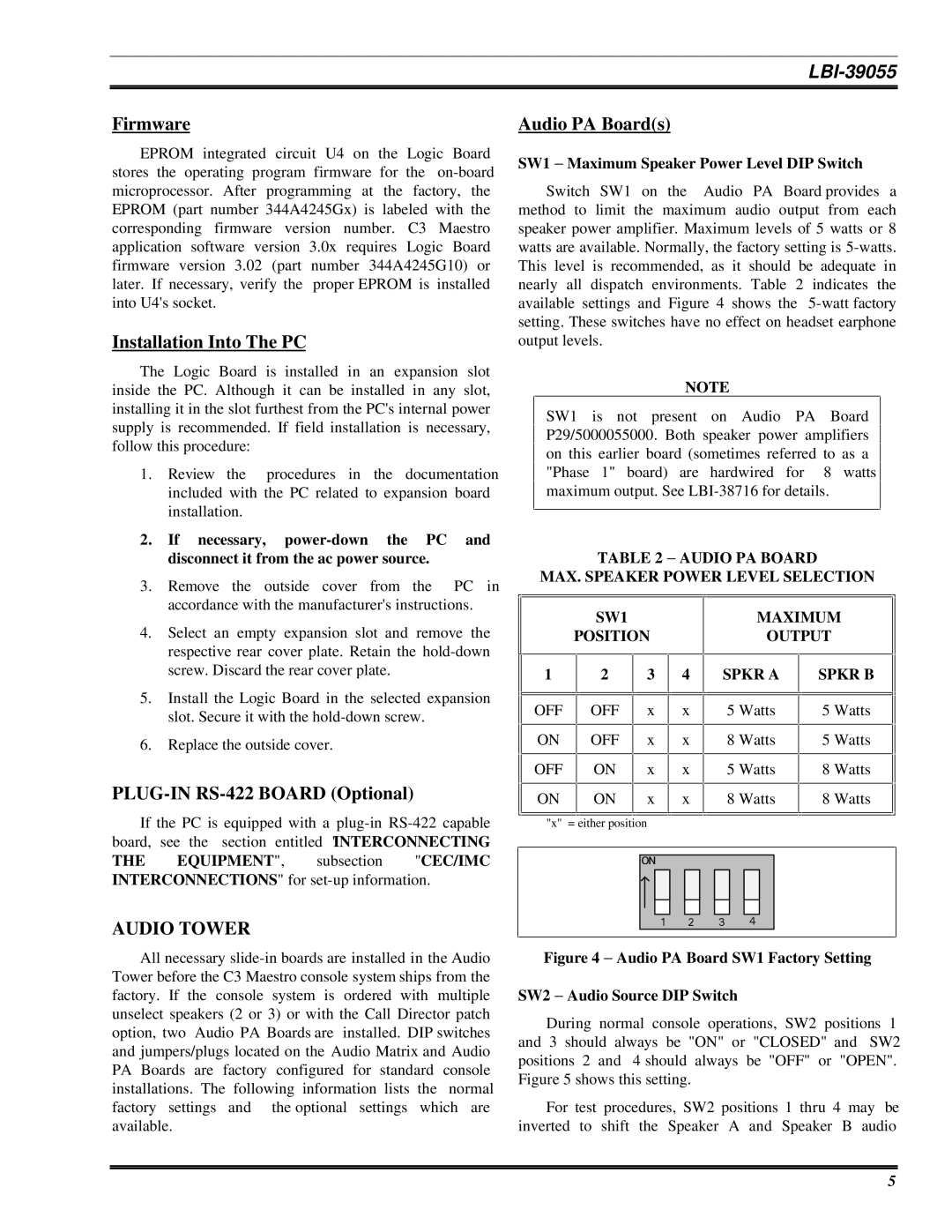
Switch SW1 on the Audio PA Board provides a method to limit the maximum audio output from each speaker power amplifier. Maximum levels of 5 watts or 8 watts are available. Normally, the factory setting is
NOTE
SW1 is not present on Audio PA Board P29/5000055000. Both speaker power amplifiers on this earlier board (sometimes referred to as a "Phase 1" board) are hardwired for 8 watts maximum output. See
TABLE 2 − AUDIO PA BOARD
MAX. SPEAKER POWER LEVEL SELECTION
4. | Select an empty expansion slot and remove the |
| respective rear cover plate. Retain the |
| screw. Discard the rear cover plate. |
5. | Install the Logic Board in the selected expansion |
| slot. Secure it with the |
6. | Replace the outside cover. |
PLUG-IN RS-422 BOARD (Optional)
If the PC is equipped with a
THE EQUIPMENT", subsection "CEC/IMC INTERCONNECTIONS" for
AUDIO TOWER
|
|
| SW1 |
|
|
| POSITION | ||||
|
|
|
|
|
|
1 |
| 2 | 3 | ||
|
|
|
|
|
|
|
|
|
|
|
|
OFF |
|
| OFF |
| x |
|
|
|
|
|
|
ON |
|
| OFF |
| x |
|
|
|
|
|
|
OFF |
|
| ON |
| x |
|
|
|
|
|
|
ON |
|
| ON |
| x |
|
|
|
|
|
|
|
|
|
|
|
|
"x" = either position
4
x
x
x
x
MAXIMUM
OUTPUT
|
| SPKR A | SPKR B | |||
|
|
|
|
|
|
|
|
|
|
|
|
|
|
|
| 5 Watts | 5 Watts | |||
|
|
|
|
|
|
|
|
| 8 Watts | 5 Watts | |||
|
|
|
|
|
|
|
|
| 5 Watts | 8 Watts | |||
|
|
|
|
|
|
|
|
| 8 Watts | 8 Watts | |||
|
|
|
|
|
|
|
|
|
|
|
|
|
|
|
|
|
|
|
|
|
|
|
|
|
|
|
|
|
|
|
|
|
|
|
All necessary
Figure 4 − Audio PA Board SW1 Factory Setting
SW2 − Audio Source DIP Switch
During normal console operations, SW2 positions 1 and 3 should always be "ON" or "CLOSED" and SW2 positions 2 and 4 should always be "OFF" or "OPEN". Figure 5 shows this setting.
For test procedures, SW2 positions 1 thru 4 may be inverted to shift the Speaker A and Speaker B audio
5