LBI-39055
∙ Modem Options |
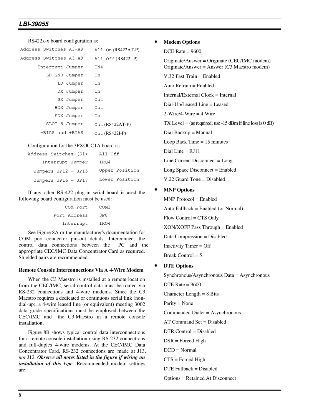
Address Switches
Address Switches
Interrupt Jumper
LD GND Jumper
LD Jumper
DX Jumper
SX Jumper
HDX Jumper
FDX Jumper
SLOT 8 Jumper
All On
All Off
IN4
In
In
In
Out
Out
In
Out
DCE Rate = 9600 |
Originate/Answer = Originate (CEC/IMC modem) |
Originate/Answer = Answer (C3 Maestro modem) |
V.32 Fast Train = Enabled |
Auto Retrain = Enabled |
Internal/External Clock = Internal |
TX Level = (as required; use |
Dial Backup = Manual |
Loop Back Time = 15 minutes |
Configuration for the 3PXOCC1A board is:
Address Switches (S1) | All Off | ||
Interrupt Jumper | IRQ4 | ||
Jumpers | JP12 − | JP15 | Upper Position |
Jumpers | JP16 − | JP17 | Lower Position |
If any other
COM Port | COM1 |
Port Address | 3F8 |
Interrupt | IRQ4 |
See Figure 8A or the manufacturer's documentation for COM port connector
control data connections between the PC and the appropriate CEC/IMC Data Concentrator Card as required. Shielded pairs are recommended.
Remote Console Interconnections Via A 4-Wire Modem
When the C3 Maestro is installed at a remote location from the CEC/IMC, serial control data must be routed via
Figure 8B shows typical control data interconnections for a remote console installation using RS-232 connections and full-duplex 4-wire modems. At the CEC/IMC Data Concentrator Card, RS-232 connections are made at J13, not J12. Observe all notes listed in the figure if wiring an installation of this type. Recommended modem settings are:
| Dial Line = RJ11 |
| Line Current Disconnect = Long |
| Long Space Disconnect = Enabled |
| V.22 Guard Tone = Disabled |
∙ | MNP Options |
| MNP Protocol = Enabled |
| Auto Fallback = Enabled (or Normal) |
| Flow Control = CTS Only |
| XON/XOFF Pass Through = Enabled |
| Data Compression = Disabled |
| Inactivity Timer = Off |
| Break Control = 5 |
∙ | DTE Options |
| Synchronous/Asynchronous Data = Asynchronous |
| DTE Rate = 9600 |
| Character Length = 8 Bits |
| Parity = None |
| Commanded Dialer = Asynchronous |
| AT Command Set = Disabled |
| DTR Control = Disabled |
| DSR = Forced High |
| DCD = Normal |
| CTS = Forced High |
| DTE Fallback = Disabled |
| Options = Retained At Disconnect |
8
