LBI-39055
These terminals are not polarity sensitive. Load resistors are not required for unused speaker outputs.
TABLE 8 − SPEAKER CONNECTIONS
UNSELECT
AUDIO OUTPUT
UNSELECT
AUDIO GROUND
(TOP)
UNSELECT
RECORDER
SPEAKER |
| AUDIO PA |
| BOARD | |
|
| |
|
|
|
|
|
|
Select | #1 * | |
|
|
|
TERMINAL
BLOCK
LABELING
SPKR A
SCREW
TER-
MINALS
upper two
SELECT AUDIO
OUTPUT
SELECT AUDIO
GROUND
SELECT RECORDER
Unselect #1 | #1 * | |
|
|
|
Unselect #2 | #2 * | |
|
|
|
Unselect #3 | #2 * | |
|
|
|
|
|
|
SPKR B
SPKR A
SPKR B
lower two
upper two
lower two
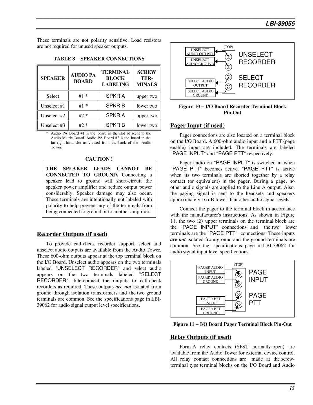
Figure 10 − I/O Board Recorder Terminal Block
Pin-Out
Pager Input (if used)
*Audio PA Board #1 is the board in the slot adjacent to the Audio Matrix Board. Audio PA Board #2 is the board in the far
CAUTION !
THE SPEAKER LEADS CANNOT BE CONNECTED TO GROUND. Connecting a speaker lead to ground will
Recorder Outputs (if used)
To provide
Pager connections are also located on a terminal block on the I/O Board. A
Pager audio on "PAGE INPUT" is switched in when "PAGE PTT" becomes active. "PAGE PTT" is active when its two terminals are shorted together by a relay contact (or equivalent) in the pager. During a page, no other audio signals are applied to the Line A output. Also, the paging signal is sent to the headsets and speakers approximately 16 dB lower than other audio signal levels.
Connect the pager to the terminal block in accordance with the manufacturer's instructions. As shown in Figure 11, the two (2) upper terminals on the terminal block are the "PAGE INPUT" connections and the two lower terminals are the "PAGE PTT" connections. These inputs are not isolated from ground and the ground terminals are common. See the specifications page in
labeled "UNSELECT RECORDER" and select audio appears on the two terminals labeled "SELECT RECORDER". Interconnect the outputs to
PAGER AUDIO
INPUT
PAGER AUDIO
GROUND
PAGER PTT
INPUT
PAGER PTT GROUND
(TOP)
PAGE
INPUT
PAGE
PTT
Figure 11 − I/O Board Pager Terminal Block Pin-Out
Relay Outputs (if used)
15